This thread has been locked.

If you have a related question, please click the "Ask a related question" button in the top right corner. The newly created question will be automatically linked to this question.

ADS1218: Data improper when giving sine wave at analog inputs of ADS1218

Part Number: ADS1218
Other Parts Discussed in Thread: ADS131M08

Hello, 

I am trying to read data from ads1218 ADC interfaced with Arduino Uno. When I have connected differential input (bridge: maximum 70 mV output )in  AIN0 (+ve) and AIN1 (-ve),  fosc=4Mhz,fmod=15.625kHz (fosc/256), PGA=1/2/128 etc ,decimation factor (default: 1920),sinc3 filter, unipolar format, I am able to read the data properly.

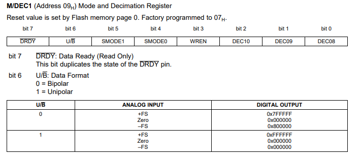
But when I am giving sine wave as an input in  AIN0 (+ve) and AIN1 (-ve) with amplitude 1.25V and DC offset of +1.25V , frequency of 100Hz (fdata= 100Hz) so decimation factor= 15.625kHz/ 100Hz=156.25. Then value of MDEC0(LSB of decimation factor) is set to 0x38 (HEX) and MDEC1 is set to 0x71(HEX) with unipolar format, sinc 3 filter. Vref used is 2.5V.  Output should come as sine wave with Vpp of 2.5 V but I am getting output always constant value of 2.5V. I have also checked the sine wave input in oscilloscope , input side it is fine. Please assist me in solving this issue.

Thank you

Regards

Sushmita Chaudhary

  • Hi Sushmita Chaudhary,

    There may be some misunderstanding about the ADC.  The ADS1218 is a Delta-Sigma ADC that oversamples the input, converts the input signal to a modulator bit stream, and then applies a low-pass filter to remove quantization error that is pushed to the higher frequencies.  So there are two things to consider.  The first is the data output rate (not the modulator frequency) should be used to determine the maximum input frequency based on Nyquist theorem.  Second, the sinc3 filter will have a 3dB rolloff that may reduce the returned ADC count.

    If your fDATA output rate is 100Hz (sps), then the maximum input frequency is 50Hz.  When using the sinc3 filter the 3dB cutoff is 0.262*fDATA or 26.2Hz for fDATA = 100Hz (sps).

    This is based on the data output rate of 100Hz (sps), but actually the data output rate is fMOD/MDEC.  MDEC is 0x138 which is 312 decimal and fMOD is 15625Hz.  This sets the data output rate to 50sps for the MDEC value selected.  You will need to adjust your input frequency and/or MDEC value accordingly.

    Best regards,

    Bob B

  • Hi Bob,

    Thanks for explanation. I will try to implement this in my code and give feedback to you.

    Regards

    Sushmita Chaudhary

  • Hi Bob,

    Thanks for the explanation. I am getting the sine wave output as per changing the sample rate and decimation factor settings. I have one small doubt regarding the bipolar and unipolar selection in the MDEC1 register setting.

    When I applied a sine wave with an amplitude of 0.5V and DC offset of 0.5V  and an input frequency of 10Hz (sampling rate used: 100sps) if I selected the bipolar setting then my data output amplitude is shifted due to 0.5V DC offset given so Vpp is coming 1V.

    But when I am applying the same signal with the unipolar setting, in this case, I am getting double the output and the number of input sine waves in 100 samples is also not able to reconstruct properly.

    Can you please explain what can be the significant change while selecting unipolar and bipolar format? And if we are selecting unipolar and if we apply a sine wave without and dc offset then internal reference(2.5V used) if enabled should shift the sine wave by 2.5V. 

    As per the datasheet, it is mentioned that if the buffer is disabled then AIN can be applicable within ( -100mV to 5.1 V (Avdd=5V)), so if I apply a negative differential signal between AIN0 and AIN1 (let's say -1 mv ) and the bipolar setting is set in MDEC1 and decimation value is 1920, PGA is 1 then in this case ADC is giving 0 output.  But since bipolar is selected then it should give a negative value output.

    Please let me know if my understanding regarding unipolar and bipolar mentioned above is correct or not.

    Thank you

    Regards

    Sushmita 

  • Hi Sushmita,

    In bipolar format the output of the conversion data are binary 2's complement with the full-scale range (FSR) as +/-Vref or +/-2.5V (5V).  For single-ended measurements where the input is measured with respect to ground, you will lose a bit as you can only measure up to positive full-scale (+FS) as AINN is fixed at ground and AINP can never go below ground.  In unipolar format the data are straight binary and you will only see positive codes for the input.  So instead of +FS limited to 0x7FFFF you can recapture the previously lost bit and can now achieve codes to 0xFFFFFF.

    So the calculation of codes to volts changes because the FSR changes from 5V (+/-2.5V) to 2.5V (+2.5V) and the result code will have 2 times the previous result when recapturing the -FS portion.  So the end result voltage should be the same if you use the correct LSB voltage value for the calculation.

    If you are in binary mode and buffer disabled you should see a slightly negative value if AINN is at 0V (ground) and AINP is slightly below ground.  This assumes that the offset calibration has removed any possible offset and you have verified that you are not still in unipolar mode by reading back the register contents.

    Best regards,

    Bob B

  • Hi Bob,

    Thank you for your explanation. I applied the signal in both modes and verified the results as per the explanation given below.

    Suppose I want to acquire data from all channels(AIN0 to AIN7) simultaneously, is it possible? But as per the datasheet, we can multiplex one input signal at a time. Is there a chance to acquire one channel and then wait for the conversion of data of the first channel and then acquire another channel,  but this may cause a delay in data and it may not be synchronized.

    So how to acquire data simultaneously from all channels without losing any data?

    Thank you

    Regards

    Sushmita Chaudhary

  • Hi Sushmita,

    The ADS1218 has a single ADC with a mux so that multiple inputs can be connected, but only one one can be converted at a time.  This approach differs from devices that contain multiple ADCs for simultaneous conversions.  The ADS1218 was designed for slow moving input signals that can be captured when cycling the mux.  If you need precise monitoring of multiple inputs at the same time, then you will need to use a different device.  Take a look at the ADS131M08 as a possibility.

    Best regards,

    Bob B

  • Hi Bob,

    Thank you for the explanation. Can we acquire one-by-one channels(maximum rate:100 Hz) by writing to the registers of ADS 1218 by selecting different inputs of MUX after giving some delay and then issuing the RDATA command and DRDY status and togging CS for getting converted 24-bit data? But whether we have to call the RDATA command multiple times for the acquisition of 24-bit data from multiple channels. 

    Thank you 

    Regards

    Sushmita Chaudhary

  • Hi Sushmita,

    The ADS1218 requires that the digital filter be settled for the correct conversion output.  This means that when using the sinc3 filter, the first three conversions are unsettled data and invalid.  The 4th conversion is settled data and is valid.  So after a muxed input channel change you must monitor DRDY for a high to low transition disregarding the first 3 and on the 4th issue the RDATA command.  This would be required after each input channel change.

    It is not clear why you chose the ADS1218.  This is an older device and is a bit more complicated to use when cycling the mux.  Using the ADS1218 it will be quite difficult to capture the conversion of 8 input signals without some degradation of the input signal being converted.  If you need to accurately represent the input AC signal you would have to cycle through the mux very quickly.  Changing the decimation to increase the speed of conversion will also increase the noise.  The quickest way to collect data would be to use the fast-settling filter (sinc1) which would only require that the first conversion after a channel change be disregarded.  You could also use the DSYNC (command or pin) to reset the digital filter immediately after the channel change which would then allow the next conversion in fast-settling filter mode to be valid.

    Best regards,

    Bob B

  • Hi Bob,

    Thank you for the detailed information. I have chosen ADS1218 (already in laboratory) due for single channel requirement but now requirement changed for upgradation to 8 channels.  I will look out for other ADC which you have shared the part number ADS131M08.

    Thank you

    Regards

    Sushmita Chaudhary