This thread has been locked.
If you have a related question, please click the "Ask a related question" button in the top right corner. The newly created question will be automatically linked to this question.
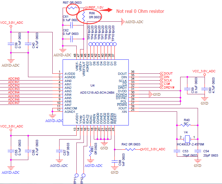
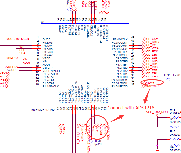
Hello, I try to use ADS1218 with MSP430. However, I can't find any code example for ADS1218. Does any one can post the code or send it to my email (wt20094324@1563.com) ? Thank you very much.
Hi user4908522,
Unfortunately we do not have MSP430 example code for the ADS1218. There may be some useful code in part of this project to get you started even though it is for a different processor:
https://e2e.ti.com/support/data_converters/precision_data_converters/w/design_notes/ads1216
The link below is for ADS1220 example code showing usage and setup of MSP430 peripherals for the MSP430F5528. This may be useful to understand device setup for SPI communication.
Best regards,
Bob B
Hi Bob,
I am sorry to bother you again. Recently I start to test the ADS1218 with MSP430F149. However, the ADC does not work. I configure the ADC SETUP register and set the voltage reference out as 1.25V. But the voltage reference output is always 2.5V. I found the SPI works well by using oscilloscope to observe the DOUT, DIN, SCLK, CS line when I send the command. The power supply of ADC is 3V. The POL pin of ADC is set high. And the SPI program and ADC configure program list below. Can you give some advice for this problem, thank you very much.
//******SPI initialization code*******//
#include <msp430x14x.h>
#include "SPI.h"
void SPI_Init()
{
// Set the pin as USART port
P3SEL|=BIT1+BIT2+BIT3;
// Stop USART
UCTL0|=SWRST;
// 8 bit mode, SPI Master
UCTL0|=CHAR+SYNC+MM;
// Chosse SMCLK as USART clock, in this program, the SMCLK=1MHz
UTCTL0|=SSEL1;
// Set the SCLK=100kHz
UBR00=0x0A;
UBR10=0x00;
// Disable UMCTL0 in SPI master mode
UMCTL0=0x00;
// 3-wire SPI
UTCTL0|=STC;
// Configure SCLK phase and polarity, 01
UTCTL0&=~(CKPH);
UTCTL0|=CKPL;
// Enable USART module
U0ME=USPIE0;
UCTL0&=~SWRST;
// Enable transimit and receive interrupt
IE1|=URXIE0+UTXIE0; //使能发送和接收中断
}
//********ADS1218 initialization and configure code*******//
//
// MSP430F149
// -------------------
// | |
// | |
// | P3.6 |<--DRDY
// | |
// | P3.3 |-->SCLK
// | |
// | P3.2 |<--SOMI(DOUT)
// | |
// | P3.1 |<--SIMO(DIN)
// | |
// | P3.0 |-->CS
// | |
// | |
// -------------------
//
//
//
// Date: 2017/09/26
#include <msp430x14x.h>
#include "ADS1218.h"
#include "Delay.h"
void ADS1218_Init()
{
ADS1218_CSHigh; // Disable ADS1218
P3DIR|=BIT0; // CS pin of ADS1218
P3DIR&=~BIT6; // DRDY pin of ADS1218
}
void ADS1218_Config()
{
unsigned char Temp;
Temp=ADS1218P0|ADS1218NCOM;
ADS1218_WRReg(ADS1218_MUX,0x01,&Temp); //Chosse channel AIN0-Acom
Temp=REFEN; // IRV=1.25V, fmod=fosc/128, Buffer Disabled, MSB Transmitted First
Temp&=~REFHI;
ADS1218_WRReg(ADS1218_SETUP,0x01,&Temp);
Temp=ADS1218PGA1;
ADS1218_WRReg(ADS1218_ACR,0x01,&Temp);
Temp=SMODE3|UB|0x03; // Select sinc3 filter, unbiopolar data format, decimation high 3bits
ADS1218_WRReg(ADS1218_DEC1,0x01,&Temp);
Temp=0xFF;
ADS1218_WRReg(ADS1218_DEC0,0x01,&Temp);
}
void ADS1218_WRReg(unsigned char StartAddress, unsigned char NumReg, unsigned char *pData)
{
unsigned char i;
ADS1218_CSLow;
ADS1218_Send(WREG|(StartAddress&0x0F));
ADS1218_Send((NumReg-1)&0x0F);
for (i=0;i<NumReg;i++)
{
ADS1218_Send(*pData++);
}
ADS1218_CSHigh;
}
void ADS1218_Send(unsigned char Data)
{
unsigned char dummy;
while (!UTXIFG0);
TXBUF0=Data;
while(!URXIFG0);
dummy=RXBUF0;
//delay 8 time of SCLK frequency
delay_us(80);
}
//********The circuit diagram of ADS1218 and MSP430F149*********//
Hi user4908522,
You have given a lot of useful information. However, with respect to communication it would be helpful for me to actually see logic analyzer of oscilloscope shots of the communication; in particular, CS, SCLK, DIN and DOUT. CS must go low and stay low throughout the entire communication transaction. Based on the information it would appear that the ADS1218 is not responding to the communication. The first place to start is to read the registers first to see if you get the default power up values. You also need to check that all power supply connections to the ADS1218 are valid (both analog and digital supplies), and RESET, PDWN, DSYNC pins are high. Also, you must have a valid clock, so verify that the crystal is truly oscillating.
Best regards,
Bob B
Hi Bob,
Thank you very much for your patiently answer. The reason for that strange phenomenon I had found. Since the power supply is controlled by MSP430 digital IO in my PCB board, after power up the ADC, it need to wait some micro sencond to write and read ADC. The final code structure as follows, then the ADC works ok.
#include "I2C.h"
#include "SPI.h"
#include "ADS1218.h"
//#include "MyChar.h"
uchar dFlag=0;
void main()
{
uchar i;
long Data;
WDT_Init();
Clock_Init();
Port_Init();
Timer_Init();
SPI_Init();
ADS1218_Init(); //Enable power supply for ADC, configure DRDY pin, Disable CS
delay_ms(600);
ADS1218_Config();
.....
Best regards!
Hi user4908522,
I'm glad to hear you found the issue. Thanks for responding and sharing your solution. This may help others with similar issues in the future.
Best regards,
Bob B