This thread has been locked.
If you have a related question, please click the "Ask a related question" button in the top right corner. The newly created question will be automatically linked to this question.
In my custom board I am using this IC ADC3660 to read the voltage input , calculate the transient values and record in NAND flash.
The ADC is controlled using SPI lines. I my case there was requirement of four ADC channel, so I have two 16bit ADCs.
In the custom board, I need to make sure that ADC is up and running, and also make sure that the values that are processed by the ADC IC is matching with the expected once.
These three things can be ensured by doing the following tests:-
0. Configuring the ADC: Through kernel how this can be achieved?
1.To see the connectivity and working of ADC is correct : XJTAG library for the IC ADC3660
2. To check the correctness of value: Write a simple application / kernel script that reads the adc and shows the corresponding values
I need help these points.
The zeroth point will make sure the sample rate ,.. are taken care of.
The first point will make sure that the ADC connections are appropriate (without firmware)
The second point will make sure that the ADC is responding to SPI and there is no discrepancy (with firmware).
Please provide me any reference with respect to these three points.
If the XJTAG library is available please share that too.
Below I am providing the snap from my schematic.
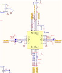
Thanks,
Sameeksh M Shetty
Hey Sameeksh,
We currently do not have any libraries written for the ADC3660 in Linux for an embedded system like this. We typically do programming SPI programming via. an FTDI chip and do sample management our capture cards in a Windows environment.
I have some additional questions for you.
1. What sample rate do you want to the run the ADC at? What kind of signals do you plan to digitize?
2. What kind of instantaneous bandwidth do you need in your system?
3. Are you using the ADC in dual channel mode?
From there I think we can figure out a way to get you a register map for the ADC that you can program into the device using a method of your choosing.
Regards,
Matt
Hi Matthew,
To answer your questions
1. The sampling rate is 10Mhz
2. Bandwidth we are targetting is 16 bit per channel.
3. We are using ADC in dual channel mode.
It will be helpful if you can provide any standard C application used for testing or FPGA source code used on EVM boards.
Hi Sarfaraz,
I have attached the required register writes for the configuration you mentioned. Like Matt mentioned, we typically program the device via SPI.
Regards, Amy
0x7 0x0 0x8 0x0 0x9 0x0 0xd 0x0 0xe 0x0 0x11 0x0 0x13 0x0 0x14 0x0 0x15 0x0 0x16 0x0 0x19 0x12 0x1a 0x0 0x1b 0x88 0x1e 0x0 0x20 0x0 0x21 0xf0 0x22 0xf 0x24 0x0 0x25 0x0 0x26 0x20 0x27 0x0 0x2a 0x0 0x2b 0x0 0x2c 0x0 0x2d 0x0 0x2e 0x0 0x31 0x0 0x32 0x0 0x33 0x0 0x34 0x0 // Bit Mapping Registers 0x39 to 0x88. For future development. 0x39 0x46 0x3a 0x4c 0x3b 0x4e 0x3c 0x54 0x3d 0x56 0x3e 0x5c 0x3f 0x5e 0x40 0x64 0x41 0x66 0x42 0x6c 0x43 0x6 0x44 0xc 0x45 0xe 0x46 0x14 0x47 0x16 0x48 0x1c 0x49 0x1e 0x4a 0x24 0x4b 0x26 0x4c 0x2c 0x4d 0x47 0x4e 0x4d 0x4f 0x4f 0x50 0x55 0x51 0x57 0x52 0x5d 0x53 0x5f 0x54 0x65 0x55 0x67 0x56 0x6d 0x57 0x7 0x58 0xd 0x59 0xf 0x5a 0x15 0x5b 0x17 0x5c 0x1d 0x5d 0x1f 0x5e 0x25 0x5f 0x27 0x60 0x2d 0x61 0x42 0x62 0x48 0x63 0x4a 0x64 0x50 0x65 0x52 0x66 0x58 0x67 0x5a 0x68 0x60 0x69 0x62 0x6a 0x68 0x6b 0x2 0x6c 0x8 0x6d 0xa 0x6e 0x10 0x6f 0x12 0x70 0x18 0x71 0x1a 0x72 0x20 0x73 0x22 0x74 0x28 0x75 0x43 0x76 0x49 0x77 0x4b 0x78 0x51 0x79 0x53 0x7a 0x59 0x7b 0x5b 0x7c 0x61 0x7d 0x63 0x7e 0x69 0x7f 0x3 0x80 0x9 0x81 0xb 0x82 0x11 0x83 0x13 0x84 0x19 0x85 0x1b 0x86 0x21 0x87 0x23 0x88 0x29 0x8f 0x0 0x92 0x0