This thread has been locked.

If you have a related question, please click the "Ask a related question" button in the top right corner. The newly created question will be automatically linked to this question.

ADS1261: ADS1261 DC measurement external reference power supply

Part Number: ADS1261

Hey Bryan,

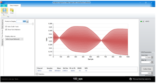
i took a DC measurement with INPMUX: temperature sensor (~0.200±0.001)V

                                                    REF: internal AVSS/AVDD      /   Laboratory power supply (5V)

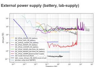
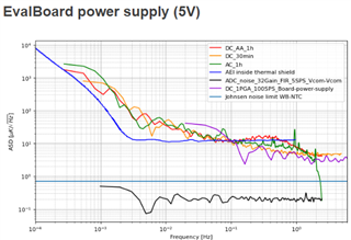
When taking the measurements i see a strong oscillation which only occurs when i use an external power supply. When using the EvalBoard on board power supply i don't see the oscillations.

Laboratory power supply 5V   &    REF: 5V lab power supply

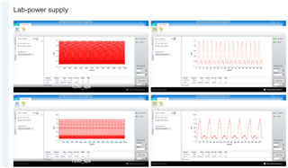
9V battery power supply  & REF: AVDD/AVSS

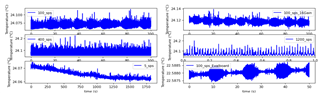
external power supplys                                              &                          EvalBoard power supply:

Questions?

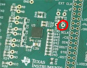
Why are the oscillations appearing ONLY when i use an external power supply ? Do i need to connect my power supply somewhere else (AIN0&AIN1 at the moment).

Best regards,

Marcel

  • Hi Marcel Beck,

    Where are you connecting the external power to the EVM? Can you describe and send a picture?

    What is the model number of the lab supply you are using?

    How is the complete system setup? Is the EVM plugged into a laptop? If so, is the laptop plugged into the wall for power, or is it floating? I.e. you might have ground loops

    -Bryan

  • Hi Bryan,

    - the external power supply is connected with the sensor(wheatstone bride) and on the AIN0 & AIN1 which are set as REF. (Simply said: the power supply is only connected with AIN0 & AIN1 on the EVM.

    - just a standard lab supply (PEAKTECH 6225 A Labornetzgerät, 0 - 30 V, 0 - 5 A, stabilisiert)

    - EVM is plugged into the laptop and the laptop is plugged into the wall.

    I don't think we have ground loops since i see the same effect when i connect my 9V battery as a power supply.

    Should i connect my external power supply somewhere else on the EVM ?

    Best regards,

    Marcel

  • Hi Marcel Beck,

    1. To clarify, you have a 5V lab supply that you are connecting to the bridge and the ADC VREF (AIN0 and AIN1), and you are seeing oscillations. But you are using the EVM power (via USB) to power the actual ADC, correct?
    2. You then use a 9V battery to power the bridge, and use AVDD/AVSS as the ADC VREF
      • Do you see the same oscillations as in the previous setup? The plots you showed looked different between the first setup and the second setup, especially since one is converted to temperature while the other is in volts and is using the EVM software
      • In this case, AVDD and AVSS are being supplied by the EVM power circuitry via USB?
      • How are you scaling the bridge output voltage when you excite it with 9V? The bridge no-load output voltage will be 4.5V, which is too large for the ADS1261 unless you level-shift this voltage down somehow
    3. Are you able to power the ADC from the same source as the bridge / VREF? At least for the first setup where you are using the lab supply?
    4. Are you still using the bridge chop / AC excitation feature during this tests? If so, can you turn this off and see if the performance changes?

    -Bryan

  • 1. Yes

    2. - Not exactly the same oscillations, but in theory i should see none.

         - Yes

         - If i apply 9V to the Wheatstone bridge (my temp sensor) i get a voltage which is close to 0.2V. If i apply 5V i get a bit less.

    3. I power the ADC from the same source(USB) if i use the excitation from the board and those measurements do not show oscillations. For the first setup, the lap supply only powers the bridge. the VREF is from the EVM and the inputs are from the bridge (~0.2V)

    4. No, not using any of those

    Best regards,

    Marcel

  • Hi Marcel Beck,

    I was not clear in my last post

    The bridge no-load output voltage will be 4.5V, which is too large for the ADS1261 unless you level-shift this voltage down somehow

    The bridge no-load common-mode voltage will be 4.5V when the excitation voltage is 9V. The differential bridge voltage will be 0V in this case, but the absolute voltage on the (+) and (-) leads of the bridge will be 4.5V when the bridge is perfectly balanced. This is too large for the ADC to support in most cases - see equation 5 in the datasheet

    Are you able to power the ADC from the same source as the bridge / VREF? At least for the first setup where you are using the lab supply?

    Here I was asking if you can power the entire setup with the lab supply: bridge, ADC, and VREF. This will require some minor modifications to the EVM. I am wondering if there is an issue with the different power sources interacting with each other

    Also, why do you want to power the bridge from a lab supply but use the ADC analog supply as the reference? Then you no longer get the benefit of the ratiometric reference voltage, so any error in the excitation voltage will be seen in the output. It does not seem like your lab supply is very high performance.

    -Bryan

  • Hi Bryan,

    i talked with an expert on that topic and you are right, the common-mode voltage exceeded the ADCs range. That was the reason why i got those oscillations. 

    Thanks a lot for the patience and the fast answers. Keep up the good work Slight smile

    Best regards,

    Marcel

  • Hi Marcel Beck,

    Glad we could help resolve this one quickly

    -Bryan

  • Hey Bryan,

    i still have a question Sweat smile

    When i connect my external power supply (like mentioned above) i get rid of the oscillation when i stay in the input ADC range and have a common ground.

    My grounding of the EVM seems to work when i connect my ground to the GND of J4.

    Is this the right way to do so?

    How can i power all (sensor and EVM) by my external supply? You mentioned about some modification... (can you please point me in the direction of the manual chapter).

    Best regards,

    Marcel

  • Hi Marcel Beck,

    The most direct way to power the ADC from an external source is to tie into the test point just before the AVDD pin. This is shown in the image below

    You would also have to remove R33.

    There is also circuitry on the EVM to apply external power - see Figure 20 if you want to choose this option.

    In general you just need to follow the schematic to make sure you are powering everything you need to power if you choose external supplies.