This thread has been locked.

If you have a related question, please click the "Ask a related question" button in the top right corner. The newly created question will be automatically linked to this question.

ADS131A04: SPI Status Register indicates there are some errors - Not enough SCLKs are sent per frame.

Part Number: ADS131A04
Other Parts Discussed in Thread: ADS1299

Hi everyone,

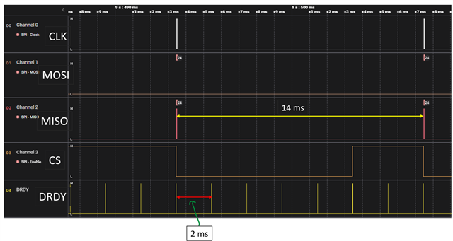
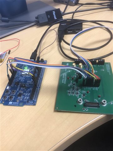
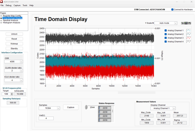
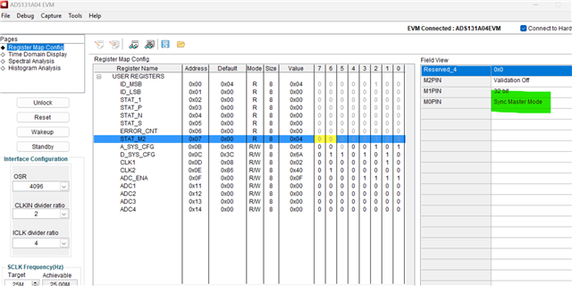
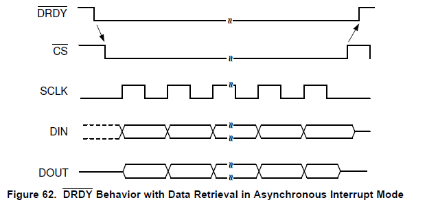
I'm trying to connect ADS131A04 Eval board with nRF52 Dev KIT. I was able to write & read all registers correctly. I'm following the instruction shared in other post to initialize and read the ADC data. I'm using Asynchronous Interrupt Mode with fixed data frame to read out the data. The following is what is supposed to see if I successfully did with this mode. The DRDY goes low when having data from DOUT (MISO).

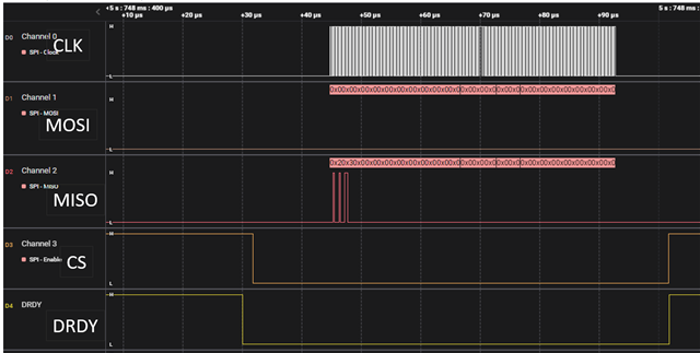
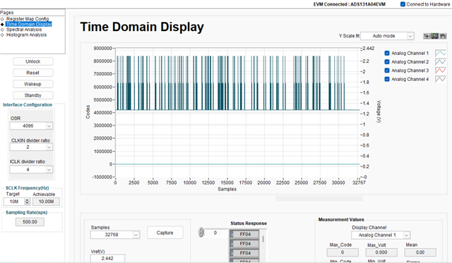
However, in my case I read data from STAT_S (SPI status register) and it showed 1 in its bit 0 - meaning that it was not enough SCLKs are sent per frame. It reflected in the following image. I'm using 4MHz for SPI's SCLK which worked well before with different ADS chip (ADS1299). Thus, I'm wondering if I set up anything wrong. My expectation is that whenever DRDY is low (every 2ms as I setup with CLK2 register), I would see data coming out from MISO pin, however, there was only 2 data sequences came out after 8 times of the DRDY goes low.

Hope to receive any suggestions from TI support team and other forum members! Thanks Tai.

  • Quick update! - I still receive a message saying it was not enough SCLKs are sent per frame. However, I removed a function that is used to process raw ADC value in the while(1) loop and I was able to receive the following result which aligns with Asynchronous Interrupt Mode data graph mentioned in the ADS131A04 datasheet. The problem right now is I wasn't able to collect ADC data from 4 channels as I consistently see 0 values in ADC channel 3 and 4 even though I try to hook some voltages to these channels. Any suggestions for this?

    Btw, regarding M pins, I put M0 --> IOVDD (32 bit device word size); M1 --> GND (using 24-bit converter); M2 --> GND (for turning off Hamming data).

  • Hi Tai Le,

    Can you read back your register settings and post them here?

    Also, can you post your .sal files instead of posting the images of them? That way I can take a look at the timing, etc.,

    Finally, did you ensure solid connections between your development kit and the A04 EVM, including the ground? It might help to see a picture to see the physical connections

    -Bryan

  • Hi Bryan. Thanks for the reply! Just wanted to make sure you know my M pin setup as the following (M pin setup --> 32-bit word size + 24bit ADC data with 8 bits zero + no Hamming code)

    For register setting:

    1. Send NULL_COMMAND --> received 0xFF04, then wait for ~5 ms.
    2. Send UNLOCK_COMMAND --> received 0x0655
    3. Configure registers:
      1. A_SYS_CFG - enable external ref Voltage
      2. D_SYS_CFG - enable fixed 6 device words & disable CRC
      3. CLK1 -- divide by 2 (fICLK = fCLKIN (using crystal - 16.384))
      4. CLK2 -- fMOD = fICLK/2 --- fDATA -- 500Hz (OSR 4096 - fDATA at 2.048 fMOD) --- I double checked DRDY pin (it correctly triggered at 500Hz).
      5. ADC_ENA -- enable all ADC channels.
    4. Send WAKEUP_COMMAND --> received 0x0033.  
    5. The sar.files are having results from register setting.
    6. As I mentioned above, I read data from  STAT_S (SPI status register) and it showed 1 in its bit 0 (0x2501).

    For ADC data reading: Please find the sar.files with all data through SPI + DRDY pin trigger.

    Please let me know if you're unable to read files I attached.

    For ADS131 Eval board connected with nRF52, here is its physical connection, I double checked its connection. I'm leaving IOVDD pin (it doesn't connect to any pins of nRF52 dev KIT). I measure the voltage of this pin at ADS131 board, it showed only 2.5V. I checked ADS131 board datasheet, it says this IOVDD is 3.3V. 

    When I was trying to connect it to external 3.3V, I couldn't receive READY response to enable the ADS131 chip. Just wondering is there anything wrong with this?

  • Somehow I don't know how to attach files. Please find them in gg drive instead. Thanks!

    drive.google.com/.../1i6Gx5XdhgV1KttRiECvleR4_Y0b9V8i1

  • Hi Tai Le,

    We are unable to access files via Google Drive. What happened when you tried to attach the .sal files? I have seen other people in the past add the file extension .csv to the .sal file e.g. "capture.sal.csv". Then I would delete the ".csv" to be able to actually open the file

    Does the EVM work fine when you use the PHI controller card instead of your development kit? In other words, can we confirm that the it is not the EVM itself that is causing issues, but it is either the physical connections with your dev kit or the code?

    Regarding the M pins: since I cannot see the bottom of your board, this means you have soldered on resistors to the correct locations to tie these pins to their respective levels?

    The IOVDD voltage needs to be connected, otherwise the ADC has no IO voltage. You are probably back driving this pin through the digital lines, but it would make sense that the ADC does not function properly without this voltage.

    -Bryan

  • I wrongly clicked "This solved my issue". Sorry!

    Regarding the M pins: since I cannot see the bottom of your board, this means you have soldered on resistors to the correct locations to tie these pins to their respective levels?

    Yes. I did solder resistors to the correct locations. 

    We are unable to access files via Google Drive. What happened when you tried to attach the .sal files? I have seen other people in the past add the file extension .csv to the .sal file e.g. "capture.sal.csv". Then I would delete the ".csv" to be able to actually open the file

    Your suggestions worked. Here you're. 

    registers setting.sal.csvSPI data - ADC reading.sal.csv

    The IOVDD voltage needs to be connected, otherwise the ADC has no IO voltage. You are probably back driving this pin through the digital lines, but it would make sense that the ADC does not function properly without this voltage.

    I see. However, as I mentioned earlier, connecting IOVDD to 3.3V, I couldn't read correctly all registers. Any suggestions for this? In the meantime, pls help me look at those sal.file and hope to receive any comments from you.  

    Does the EVM work fine when you use the PHI controller card instead of your development kit? In other words, can we confirm that the it is not the EVM itself that is causing issues, but it is either the physical connections with your dev kit or the code?

    I haven't plugged it to the PHI controller yet as this is a brand new and I assumed I worked correctly.

  • Hi Tai Le,

    Thanks for sharing the .sal info, I am glad that this method works.

    Can you hook up the EVM with the PHI controller and make sure it operates as intended? Please configure the ADC / EVM exactly as you are going to configure it with your dev kit - including power supplies, input signals, etc. - and make sure that the ADC can convert properly. This way we can confirm that there is no issue with the EVM.

    -Bryan

  • Thanks, Bryan! I'll do it and keep you posted. Please don't block this thread early. I'll get back to you once I test the EVM. Thanks.

  • Hi Tai Le,

    I believe these threads get locked after 30 days of inactivity, so you should be fine.

    -Bryan

  • Hi Bryan,

    I'm using the PHI controller to control the EVM. Before I actually connected M1 to GND (24-bit word size), however, the code I made was sent 32-bit word size via SPI. With M0 --> IOVDD; M1--> GND and M2--> GND, using the PHI controller works fine as shown in the following image.

    I then changed M1 connect to IOVDD to have 32-bit word size, using the PHI controller again. However, it didn't show any ADC values. Moreover, the STAT_M2 register keeps showing M1 connect to GND instead (Sync Master mode). I double checked it on the EVM, M1 actually connected to IOVDD (Async Mode).

  • Hi Tai Le,

    The EVM does not support 32-bit mode, see the comment below from the user's guide.

    Can you try this same configuration (24-bit word size) with your dev kit and code to see if it works any better?

    -Bryan

  • Brilliant! I'm checking it right now. Thanks, Bryan!

  • Bryan. I changed my code to send 24-bit word size; however, I still keep receiving 0xFF08 instead of 0xFF04. The following is sal.file attached. From my understanding, I should expect to have READY response as soon as the ADS131 chip is powered on. Is that correct?new register setting.sal.csv

  • Hi Tai Le,

    Let me look into this today and get back to you

    -Bryan

  • I somehow managed to receive DRDY response. I did it by adding 3.0V instead of 3.3V to IOVDD pin. I'm still not sure why did that happen. I was able to write/read registers successfully.

    The following sal.file is my ADC data. With 24-bit word size, I disable CRC and chose dynamic data frame. I'm reading 15 bytes, including 3 bytes of status response and 12 bytes of 4 ADC channels. I still got an error of SPI F_FRAME fault. Right now, DRDY triggers every 2 ms, but SPI is 5 times slower with 10 ms for 2 consecutive data transmission. I've read several posts in the forum regarding F_FRAME error, but haven't figured it out yet.

    SPI dat - 24-bit word size - F_FRAME fault.sal.csv

  • Hi Tai Le,

    I am glad you are making progress. Did the data that you received from the ADC match the input voltages you applied to the device? In other words, was the data correct (other than the FRAME fault)?

    Why are you not bringing CS high once the data transaction is complete (all 5 words, or 15 bytes, are clocked out)? And why are you not reading data again once DRDY drops low every 2ms?

    -Bryan

  • Hi Bryan,

    I was able to solve the problem of mismatch between frequency of DRDY and SPI. Just commented all printf lines in my SPI data handler and it helped speed up the SPI.

    Although I was able to get ADC data correctly (I put a sine wave to the ADC input and read it out correctly), the FRAME fault still happened when I read data from that register. 

  • Hi Tai Le,

    Okay, good to know about the printf statements. Those are usually very resource-intensive and can currently cause other interrupts to be missed.

    So now it seems like everything is working as expected, except that you are still getting the F_FRAME fault - is that correct?

    If so, there is a comment in the datasheet about the F_FRAME fault that I have copied below. Since you are using dynamic-frame mode, this comment should apply to your situation. I would interpret this to mean that you can effectively ignore the F_FRAME fault as long as you are able to successfully read out data and the rest of the STATUS bits

    -Bryan

  • Got it. Thank you so much for your help, Bryan!

  • Hi Tai Le,

    No problem, glad we could help

    -Bryan