Other Parts Discussed in Thread: , ADS1291
Hello,
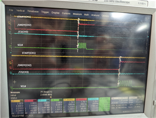
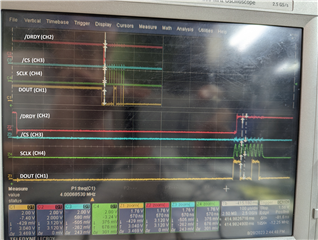
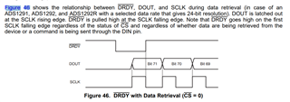
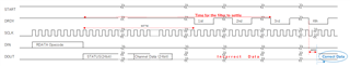
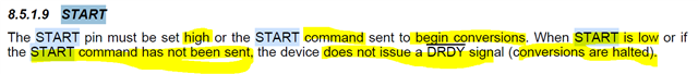
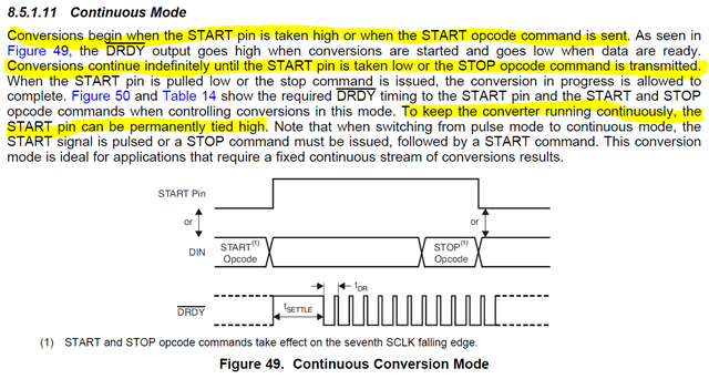
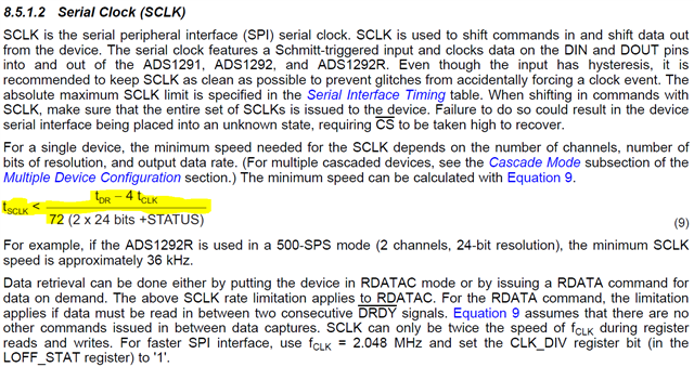
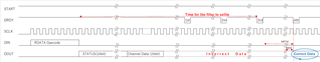
My customer has incorrect data acquisition issue from ADS1292 by RDATA command with START=Hi by pull-up resistor. Please see "AFE Circuit.pdf" how ADS1292 devices(they use 2 devices) are connected and "ADS1292 AFE data acquisition issue.xlsx" showing the issue in detail Would you please elaborate me what the reason their system doesn't work well would be and the method how they can fix the issue? The datasheet shows /DRDY and RDATA in multiple places, so it confuses me as well as my customer how /DRDY and RDATA need to be.
AFE Circuit.pdfADS1292 AFE data acquisition timing issue.xlsx
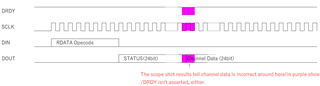
It seems they sometimes read out like the followings. They confirmed the incorrect data weren't noise.
1 2 3 4 5 6 <- expectation
1 2 2 4 5 6
1 2 3 4 4 6
1 2 4 4 5 6
They even sometimes read out data like this.
1 2 3 9 5 6
Note that they confirmed the timing for SPI is no problem. Note also that their system configures as shown below.
AFE#1
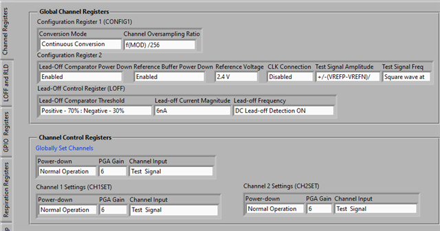
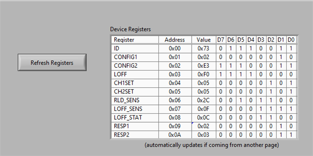
0x02, // CONFIG1
0xE0, // CONFIG2
0x90, // LOFF
0x00, // CH1SET
0x80, // CH2SET
0x00, // RLD_SENS
0x03, // LOFF_SENS
0x00, // LOFF_STAT
0x02, // RESP
0x03, // RESP2
0x0C // GPIO
AFE#2
0x06, // CONFIG1
0xA0, // CONFIG2
0x90, // LOFF
0x10, // CH1SET
0x90, // CH2SET
0x00, // RLD_SENS
0x00, // LOFF_SENS
0x00, // LOFF_STAT
0x02, // RESP1
0x03, // RESP2
0x0C // GPIO
Best Regards,
Yoshikazu Kawasaki