This thread has been locked.

If you have a related question, please click the "Ask a related question" button in the top right corner. The newly created question will be automatically linked to this question.

AFE5809EVM: AFE5809EVM DEMOD 输出不正常

Part Number: AFE5809EVM
Other Parts Discussed in Thread: AFE5908, AFE5809

Hi All,

I have a problem with the AFE5809EVM, the AFE5809EVM is triggered in sync with the TSW1400EVM.
For Ramp tests, the test results are normal. The signal is also normal for sinusoidal test mode, but for demod models
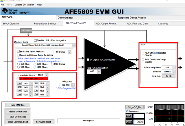
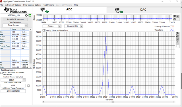
Decimation=4, I think the signal from demod is not normal. My input signal is a 10MHz, 20cycles sine burst signal, the clock signal is using 40MHZ, 3VPP external sinusoidal signal, the problem is that in DEMOD mode, I think the output signal should be a sine wave output, But actually only one signal like a triangle wave, is my understanding problematic?
Can you tell me what the AFE5908 LVDS output signal should look like in the DEMOD model when the input signal is a sinusoidal signal and what the acquired signal looks like?

THX.

  • Hi Eric,

    I recommend you to try to go step by step. First you can bring up the AFE without demod. Dont enable the demod and try to digest the output signal behavior. First you can calculate the total TGC path gain (it will LNA gain + PGA gain + TGC attenuation decided by Vcon) and based on the input signal, you will be able to calculate output signal swing. The ADC full scale swing is 2Vpp. For example if TGC gain is say 40dB then for getting 2Vpp at the output, you have to apply 20mVpp signal only. If you give signal more than this then signal chain will overload and you will see clipped output. In case you dont want to apply external Vcon then try out with DTGC attenuation setting given in the GUI.

    Once you are comfortable with signal transfer function without demod, then enable the demod and based on mixer and decimation filter setting, the signal FFT will chnage. So you need to analyze first what is expected signal at the device output based on what setting you apply for mixer and decimation filter and then capture the device data. Also you have to separate the I/Q phase data in the GUI to make sense out of it.

    Thanks

    Regards,

    Shabbir

  • Hi Shabbir,

    picture 1 is my TGC gain configuration .and the input signal is a burst sinus signal with 10 cycles and it is amplitude about 50 mV. the afe5809 LVDS output without demod just like the picture 2,

    for the output wave,it is not  so good because i use many cable instead of SMA cable to connect the evm so i think it normal. but when i want to test the demod ,the out put is so bad ,please check it from picture 3.

  • Hi,

    Are you apply TX_TRIG to the device and apply hardware trigger for capture? To separate the data, SYNC word is required. If TX_TRIG is not applied then SYNC word wont appear in LVDS data and data separation wont work.

    Also send me the steps you are following to configure the demod.

    Regards,

    Shabbir

  • Hi

    I indeed apply the tx_trig signal from the AFG3102 (signal generator),and I enable the trigger mode of the afe5809evm ,this is what the tsw1400evm sampled data. And after i enable the demod mode the output just like this.

  • Hi,

    This looks expected. Can you please show the separated data (Zoomed wavefrom)? Also share demod settings.

    Thanks!

    Regards,

    Shabbir

  • Hi Shabbir

    This is the separate data.

    The demos setting is decimation=4,I just test it by refer the Ti AFE5809evm user guide. All the setting I did just as the same as it.

    www.ti.com.cn/.../slou338a.pdf

    Thanks.

  • Hi

    I am not able to see the signal. Can you please zoom the time axis and show?

    Regards,

    shabbir

  • Hi Eric,

    Since I am supporting you by connecting to your system, I am changing the thread status.

    Thanks!

    Regards,

    Shabbir