This thread has been locked.

If you have a related question, please click the "Ask a related question" button in the top right corner. The newly created question will be automatically linked to this question.

ADS1299: ADS1299: Enabling both LOFF_SENSN and LOFF_SENSP when doing AC-based LOFF/impedance measurement?

Part Number: ADS1299

Hi there,

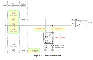
I've spent a fair amount of time trying to figure out how to implement Figure 35 in the SBAS499C-pdf - the "Lead-Off Detection".

The text in section "9.3.2.4.3 Lead-Off Detection" reads:

"Lead-off can be selectively done on a per channel basis using the LOFF_SENSP and LOFF_SENSN registers."

However, it's not clear to me if I should enable both excitation signal switches (LOFF_SENSN and LOFF_SENSP)?

Does the current flow from LOFF_SENSN to LOFF_SENSP?

Or does it depend on whether or not the BIAS-output (also on Figure 35) is enabled?

According to this post, https://e2e.ti.com/support/data-converters-group/data-converters/f/data-converters-forum/1168088/ads1299-can-i-engage-bias-loop-which-reduces-common-mode-noise-in-impedance-measurement-mode/4394754, it is claimed that it may but done without the BIASOUT:

"So, customers could try/test how the AC Lead-off detection works(in terms of sensitivity and stability) as when you attach or detach the BIASOUT electrode/patch from UUT and/or turning On/Off the BIAS Amp."

  • I just found the post https://e2e.ti.com/support/data-converters-group/data-converters/f/data-converters-forum/720944/ads1299-calculation-of-electrode-impedance-using-loff-ac-current-source. Here, Ryan states: 

    "The lead-off current is generated from current sources on each input pin. For each pair of inputs per channel, one pin will source current while the other pin will sink current of the same magnitude. The AC lead-off feature uses the same current sources as the DC lead-off feature, but the direction of the current is swapped back and forth to produce a square wave. Therefore, the current flowing from INxP to INxN will either be +6 nA or -6 nA at any given moment."

    I read that as I should have both switches enabled. But that is not how it is explained here:
    http://eeghacker.blogspot.com/2014/04/openbci-measuring-electrode-impedance.html

    The difference may be the presence of the BIAS-drive in the latter setup.

    Still confused Slight smile

  • Hi,

    You need to close/short switch

    LOFF_SENSP if you want to do lead on/off detection for INP

    LOFF_SENSN if you want to do lead on/off detection for INN

    if you want to do lead on/off detection for both INN and INP, then close/short both switches.

    Thanks

  • Hi ChienChun Yang,

    Thanks for the reply.

    So, if I only want to do lead on/off on one side, and consequently then only turn on one of the LOFF_SENSx, will the driven current thereby be half (e.g. only from 0 to 6nA, instead of -6nA to 6nA), and thereby also the voltage-amplitude only be half?

    Thanks.

  • Hi,

    I am not quite sure I understand your question. Could you explain more?

    Thanks

  • Hi,

    I'm referring to what Ryan wrote - also referred above:

    "The lead-off current is generated from current sources on each input pin. For each pair of inputs per channel, one pin will source current while the other pin will sink current of the same magnitude. The AC lead-off feature uses the same current sources as the DC lead-off feature, but the direction of the current is swapped back and forth to produce a square wave. Therefore, the current flowing from INxP to INxN will either be +6 nA or -6 nA at any given moment."

    From that, I read it requires enabling both current sources (using both inputs of a channel) to generate an alternating current +-6nA. And consequently, if I only enable one of them, I only get half that square wave (either sourcing or sinking 6 nA for half the period, and no current flowing for the second half of the time).

    I'm sorry, if it is still not clear what I mean.

  • Hi,

    I still don't understand what might be your question or concern?

    There is no question sentences nor question marks.

    May I ask what are you or do you want to ask?

    What do you mean by "only enable one of them"?

    ---------------------------------------------------------------------------------------

    Lead off detection can only be either DC  or AC not both.

    For AC lead off detection -

    "The ac signal is generated by alternatively providing a current source and sink at the input with a fixed frequency."

    AC lead off detection doesn't allow user to do/select sink or source. AC lead off detection keep switching the internal switches(ILEAD_OFF in Figure 35) on and off to produce square wave signals. User can only change the magnitude and frequency.

    And, AC lead off detection doesn't have threshold nor flag nor indication to tell Lead on or off, it requires users to do post DSP and algorithm to judge/make decision whether lead is on and off in firmware or software. 

    Thanks

  • Hi ChienChun,

    Sorry for the confusion.

    I'll try again:

    I have a setup like depicted in Figure 35:

    I'm want to figure out how the two switches "LOFF_SENSP" and "LOFF_SENSN" should be configured if I want to measure the impedance (here modeled by the 51 kOhm + 47 nF).

    If I switch on both the switches, I reckon the signal generator will behave as Ryan has explained:

    The signal generator on the positive electrode path will source current with an alternating frequency (FLEAD_OFF) and with an "amplitude"/current alternating between 6nA and 0nA (or whatever is configured in ILEAD_OFF), and the signal generator on the negative electrode path will sink current with the opposite phase, namely 0nA and -6nA.

    Q1) The result is a square-wave current flow running between +/-6nA, right?

    (That's how I've understood Ryans explanation and Figure 35 - "For each pair of inputs per channel, one pin will source current while the other pin will sink current of the same magnitude").

    Now, if that is correct, I can proceed to the next part of the question:

    Q2) What role does the presence of (or lack of same) bias-out play in the above scenario, where both LOFF_SENSx switches are closed/shorted? (also related to question below)

    But then finally:

    The setup I've outlined above - with both LOFF_SENSx switches closed does not resemble the explanation in http://eeghacker.blogspot.com/2014/04/openbci-measuring-electrode-impedance.html. Here, only one of the switches, LOFF_SENSx, is closed.

    Instead the current is sinked from, or sourced to, the bias-line (depending on which LOFF_SENSx is closed).

    Q3) In that situation, is it then correct to expect the current to be half that of the setup where both LOFF_SENSx are shorted, and thereby half the voltage compared to before? (since the current flow only alternates between 0nA and either +/-6nA)

    I hope this was somewhat more clear. I not, I'll just try again... Thanks for your patience.