


ADC ADS61B23 Custom Word configuration.
Documentation incorrect for Custom Word configuration.
Investigation revealed the bit[8] of the ADC word is unreachable (cannot be configured to anything other than ‘0’). Investigation include full analysis of REG 0B & REG 0C of the ADC. As part of the investigation for both LOW and High Pattern configuration words were tested at all possible bit positions. Testing all possible configurations the position of the LOW pattern needs to align to REG 0B bits[8:2] not as indicated in the data sheet bits[10:4) and the High Pattern needs to align to bits[4:0] of REG 0C, all other configurations produced unusable results. The current state of the ADC will allow for any custom pattern that does not require bit[8] of the ADC interface to be asserted. This is less than desirable not being able to generate bit patterns that need to assert D[8].
Scope captures and detailed analysis of unusable results was omitted as it would not likely produce any usable data.
- Adjusted the Custom Low Pattern word configuration positioning to REG 0B D[9: 2] (datasheet D[10:4]
- Adjusted the Custom High Pattern word configuration positioning to REG 0C D[6:2] (datasheet D[4:0]
a). Initial Test settings only utilized LOW Pattern settings and High Pattern set to “00000”.

Low Pattern set to 7’b0000001 0x01 High Pattern 0x00
- No Problem output as configure
Low Pattern set to 7’b1011001 0x59 High Pattern 0x00
- No Problem Output as configured
Low Pattern set to 7’b1111111 0x7F High Pattern 0x00
- No Problem Output as configured
Adjusted the Custom Low Pattern word configuration positioning to REG 0B D[9: 2] (datasheet D[10:4]
Adjusted the Custom High Pattern word configuration positioning to REG 0C D[6:2] (datasheet D[4:0]
Low Pattern set to 7’b0000001 0x01 High Pattern 5’b00001 0x01
- Output 0x001 expected 0x101
Low Pattern set to 7’b0000001 0x01 High Pattern 5’b00011 0x03
Receiving 0xC for High Pattern indicates High Pattern should be positioned at REG 0C D[4:0]
Repeat test after repositioning High Pattern at D[4:0]
- Repeated Test with adding High Pattern to Started investigation using suggestion.
- Adjusted the Custom Low Pattern word configuration positioning to REG 0B D[9: 2] (datasheet D[10:4]
- Adjusted the Custom High Pattern word configuration positioning to adc_config_array[5][10:0] <= {adc_gain[2:0], 2'b00,adc_test_pattern_high[7:2]} ;
- LSB not utilized, High pattern bit [0] cannot be programmed to ‘1’ always stuck at ‘0’ when outputting custom pattern.
Low Patterm 0x55
High Pattern 0x00
Low Pattern 0x55
High Pattern 0x01
Same results as previous with High Pattern set to 0x00 – bit[8] non-reachable through configuration.
%%%%%%%%%%%%%%%%%%%%%%%%%%%%%%%%%%%%%%%%%%%%%%%%%%%%%%%%%%%%%%%%%%
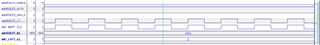
Low Pattern 0x55
High Pattern 0x02
Correct output High Custom pattern does not utilize bit[8].
%%%%%%%%%%%%%%%%%%%%%%%%%%%%%%%%%%%%%%%%%%%%%%%%%%%%%%%%%%%%%%%%%%
Low Pattern 0x55
High Pattern 0x1F
Again bit D[8] not asserted
