This thread has been locked.

If you have a related question, please click the "Ask a related question" button in the top right corner. The newly created question will be automatically linked to this question.

ADS131M03: SPI Issues Attiny84 & ADS131M03

Part Number: ADS131M03

Good afternoon, everyone!
I am doing a student project where I need to get data from a 3 channel ADC ADS131M03 using an Attiny84 microcontroller.

My problem is that I can't read any data from any of the registers, and I can't even understand if the problem is in circuit design or a program code.
Please help me to figure this out.
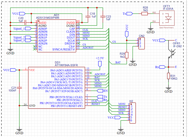


Schematic of my device.

Attiny84 -> ADS131M03 

MOSI     -> DI

MISO     -> DO

SCK       -> SCLK

CKOUT  -> CLKIN

GND      -> CS

I switch the CS manually as I use the SPI bus to program the microcontroller as well

I use Arduino IDE for desing code and "Arduino as SPI" as programmer.

Also I used AVRDUDE to program fuses of Attiny84.

In my code I am trying to read all 23 registers one by one and send this data to Serial Port.

My code:

#include <tinySPI.h>
#include <SoftwareSerial.h>

// Definitions
#define rxPin 9
#define txPin 10
SoftwareSerial mySerial(rxPin, txPin);

uint8_t reg = 0x00;
//Functions
//Transfer 24bit word to ADS131M03 
uint32_t spiTransferWord(uint16_t inputData) {
  uint32_t data = SPI.transfer(inputData >> 8);
  data <<= 8;
  data |= SPI.transfer((inputData<<8) >> 8);
  data <<= 8;
  data |= SPI.transfer(0x00);

  return data << 8;
}
//Read 1 register from ADS131M03 using RREG command
uint16_t readSingleRegister(uint8_t reg) {
  uint8_t commandPref = 0x0A;

  // Make command word using syntax found in the data sheet 101a aaaa a000 0000
  uint16_t commandWord = (commandPref << 12) | (reg << 7);

  uint32_t responseArr[5];

   // Send the command in the first word
  responseArr[0] = spiTransferWord(commandWord);

  // For the next 3 words, just read the data
  for (uint8_t i = 1; i < 5; i++) {
    responseArr[i] = spiTransferWord(0);
  }

  //Safe register data
  responseArr[0] = spiTransferWord(0);

  return (responseArr[0] >> 8);  // Extract the 16-bit data from the response
}

void setup() {
  mySerial.begin(1200);
  mySerial.println("Program started");

  SPI.begin();
  SPI.setDataMode(SPI_MODE1);
}

void loop() {
  reg++;
  if(reg > 23){
    reg = 0;
  }

  uint16_t reg_data = readSingleRegister(reg);

  mySerial.print("Register data: 0x");
  mySerial.println(reg, HEX);
  mySerial.print("Register data: 0x");
  mySerial.println(reg_data, HEX);

  mySerial.println("*****************");
  delay(1000);
}


As I understand it, I need to send a 24-bit word with a 16-bit command in it.
Then send any commands to get 5 words of response, and the 6th word should be the register data.

I Programmed CKOUT Fuse of Attiny84 to set(PCINT10/INT0/OC0A/CKOUT) PB2 pin as frequency generator with 8Mhz. 
I don't have an oscilloscope to check this signal quality.


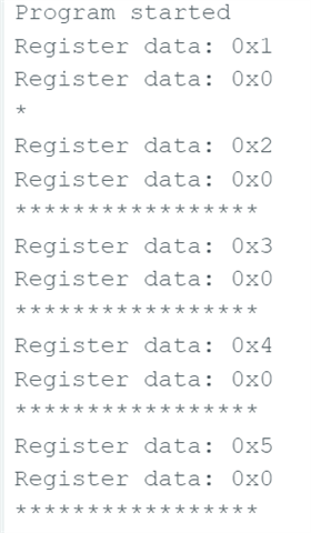
Results with CS of ADC to GND: //some random values
Results with CS of ADC to VCC://seros
  • Hello,


    In order to debug this sort of problem properly it is essential to monitor the communication lines so you can verify if there are any problems with the hardware, so I would recommend you check the communication with an oscilloscope or logic analyzer.

    Other than this, I did notice a small logic error:

    uint32_t spiTransferWord(uint16_t inputData) {
      uint32_t data = SPI.transfer(inputData >> 8);
      data <<= 8;
      data |= SPI.transfer((inputData<<8) >> 8);
      data <<= 8;
      data |= SPI.transfer(0x00);

      return data << 8;
    }

    It looks like you have an extra byte shift on your spiTransferWord function so that the readback of your data will always be left-justified.

    Levi DeVries

  • Hello!

    Since last time, I've changed the connection between MOSI and MISO. Initially it was connected incorrectly.
    This corrected the error of completely random values, because the DO of the microcontroller was connected to the DO of ADC.
    I found this out with the help of an oscilloscope, because the MOSI of the Attiny84 microcontroller was unexpectedly DI, while MISO was DO

    However, now I have a different problem.
    I got access to an oscilloscope, and this is what I have:


    1MHz signal at the CLKIN ADC input.

    1MHz signal at the CLKIN ADC input.

    Recommended Operating Conditions from datasheet

    fCLKIN External clock frequency

    +----------------------+------------------+-------------------+-------------------+
    | Mode                           | Minimum (MHz) | Nominal (MHz) | Maximum (MHz) |
    +----------------------+------------------+-------------------+-------------------+
    | High-resolution mode  | 0.3                     | 8.192                | 8.4                       |
    +----------------------+------------------+-------------------+-------------------+

    CS of ADC is always on GND 

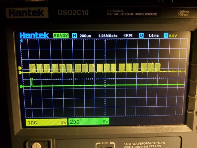
    Unfortunately, I only have a 2-channel oscilloscope. Therefore, I will send different pictures of MOSI (CH2) + CSK (CH1) and video of MISO (CH2) + CSK (CH1) measurements.

    Signal on the MOSI leg of the microcontroller. I send a command to read register 0 (1010 0000 0000 0000 0000 0000) once per second

    Signal on the MOSI leg of the microcontroller.
    I send a 24 bit word command to read register 0x00 (A0 0000) once per second

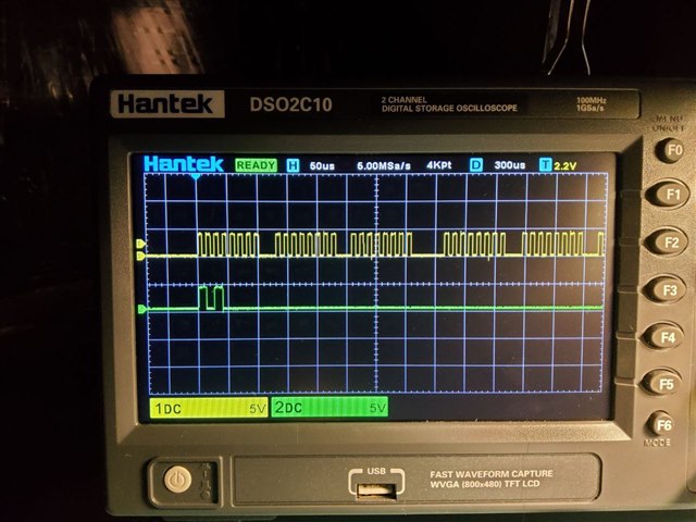
    Same as above on a different scale.

    Same as above on a different scale.

    https://youtu.be/RutCUdXQ6C4

    video with SCLK + MISO Measurements

    As I mentioned above, once a second I send a read command in a 24 bit word (0xA0 0000), and after this word I send 4 more words with zeros to complete a 5 word frame, +1 word during which I expect to get a response. However, each time I get different data from ADC, even though the command is the same from time to time.

    Please help me figure this out, I don't know what I'm doing wrong anymore.

    Regards.

  • Hello,

    Could you try using only one full frame for sending commands? The device expects only 5 words per frame with the read command you have configured, so it might be corrupting the communications if you operate the device while interrupting a frame like this. You can do this by either waiting the full one second each frame for the timeout, or you can bring the CS line high between frames.

    Additionally, I cannot read the MISO data from your scope shot, if you could zoom in the scale or provide the data readout for the whole frame I think that information would be helpful for debugging.

    Thanks,

    Levi DeVries

  • Hello!

    I realised what the problem was. Every command I received a response 0xFF23. In the Datasheet I realised that this is the ADC reset signal. The problem was that I didn't realise that the microcontroller output, which was connected to the RST of ADC, was always 0.
    I fixed it with the code and now everything works.

    At the end of the day I had 3 errors.  
    1) I connected MOSI and MISO incorrectly.
    2) I did not specify HIGH on the microcontroller output to prevent ADC reset.
    3) As you rightly said - the shift to the left by 8 bits was absolutely unnecessary.

    The delay between frames turned out to be unnecessary, apparently ADC itself determines the limit of 5 words. 

    Big thanks for your help!
    Now I have to write a code to get measurements
    .
    Regards, Ihor Shybka