This thread has been locked.

If you have a related question, please click the "Ask a related question" button in the top right corner. The newly created question will be automatically linked to this question.

ADC3683: Using Testpattern when Digital Bypass disabled

Part Number: ADC3683

Hi,


When I enable test pattern and enable digital bypass, I can see the test pattern in my FPGA debugging environment.

But with bypass disabled. There is no test pattern anymore, just raw ADC data (same with test pattern off and digital bypass on).

Is it possible to use the test pattern with digital bypass disabled?

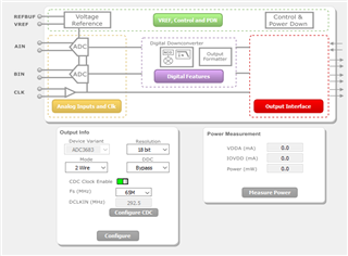
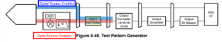
According to the datasheet figure 8-48 and also the ADC35XX EVM GUI graphs, this should be possible, but I see a different behaviour.


I'd appreciate any hints.

  • Hi Robert,

    I am looking into this. Can you please share the clock frequency and dclk frequency you are using, as well as the register writes or GUI steps you are using to configure the part?

    When you say, "bypass disabled", do you mean that the part is being put into one of the decimation modes?

    Best regards,

    Drew

  • Hi Drew,

    Thank you for looking at this.

    CLKP is 20 MHz

    DCLKP is 292,5 MHz

    FS is 65 MHz

    I'm using the GUI with following steps.

    - in "Home" tab

    --> press "Configure CDC" button

    - in "Analog Inputs and Clk" tab

    --> change Test Pattern for both channels to "Custom"

    --> change Custom Pattern to 13

    - in the "Digital Features" tab

    "Bypass Digital" is by default enabled

    After this step I can see the Custom Pattern 13 in FPGA

    now with changing the "Bypass Digital" switch, I would expect still seeing the testpattern. But I see raw adc data.

  • Hi Robert,

    Thank you for this information. I really appreciate the detail you provided.

    If you could give me a day or two to check this out that would be appreciated.

    Best regards,

    Drew

  • Hi Robert,

    Could you send a screenshot of the capture you are seeing for the custom test pattern and then the raw data capture as well?

    Best regards,
    Drew

  • Hi Robert,

    I believe I am seeing the same issue that you are. I have tried it with the ramp pattern and I see the ramp pattern when digital bypass is enabled and then I see raw ADC output when I disable the digital bypass. One thing I found was if I program real decimation (which requires digital bypass to be disabled, i.e. 2x decimation, and change DCLK to 146.25 MHz, the test pattern came back.

    I am not sure why test patterns are not coming through once digital bypass is disabled. I will reach out to the design team for some input on this. It may take a day or two to get feedback on this.

    Best regards,

    Drew

  • Hi Robert,

    I am still waiting for some feedback on this. The design team has been on holiday recently causing delay.

    Thank you for your patience.

    Best regards,

    Drew

  • Hi Robert,

    The test pattern, with digital bypass disabled, is expected to be used with the DDC. Without DDC enabled and appropriate settings configured, the test pattern will not output.

    When digital bypass is disabled, the signal is routed through the DDC where the NCO and Decimation filter is located. Thus, to get through this block, the decimation filter must be configured.

    I hope the figure below makes this clear.

    To add one more note, even though the test pattern generator is after the DDC block, the reason it won't work with digital bypass disabled is that it requires a "clock" to operate. In digital bypass mode, this is the ADC sampling clock. When digital bypass is disabled, this is no longer the case, and the DDC outputs a clock (which is a function of decimation factor) to be used for the down-stream processing.

    Best regards,

    Drew

  • Hello Drew,

    Thank you very much for your efforts.

    I don't get why the TestPatternGenerator is dependend of DDC, because in the figure these components are independend. The blue and red datapath is routed to the mux which is connected to the TestPatternGenerator.

    Is this mux really working as you described?

    So which route is the data running trough if digital bypass disabled, DDC disabled and Testpattern enabled? I would expect the route in the figure below.

    Best regards,

    Robert

  • it looks like that the figure 8-48 and figure Digital Features from GUI doesn't fit together.

    e.g.

    the TestPattern Generator:

    - in GUI it's placed in "Analog Inputs and Clk" before "Digital Features" block

    - in figure 8-48 it's placed after NCO which is part of "Digital Features" block

    the scrambler:

    - in GUI it's part of "Digital Features" block before the "Digital Bypass Mux"

    - in figure 8-48 it's after the "Digital Bypass"

    it's really confusing

  • Hi Robert,

    Unfortunately, the GUI doesn't really do the ADC any justice internally.

    The ADC must be configured as follows:

    Enable either the bypass path or DDC path. If you use the DDC path, you must enable & configure the DDC.

    Then, in either case, you can use/enable the digital test pattern block.

    Regards,

    Rob