This thread has been locked.

If you have a related question, please click the "Ask a related question" button in the top right corner. The newly created question will be automatically linked to this question.

ADS114S08: Startup Overshoot on negative power supply

Part Number: ADS114S08
Other Parts Discussed in Thread: LM25575, LM27762, , ADS1261,

Please also refer to my previous thread about LM25575 startup glitch as it is somewhat related to this.

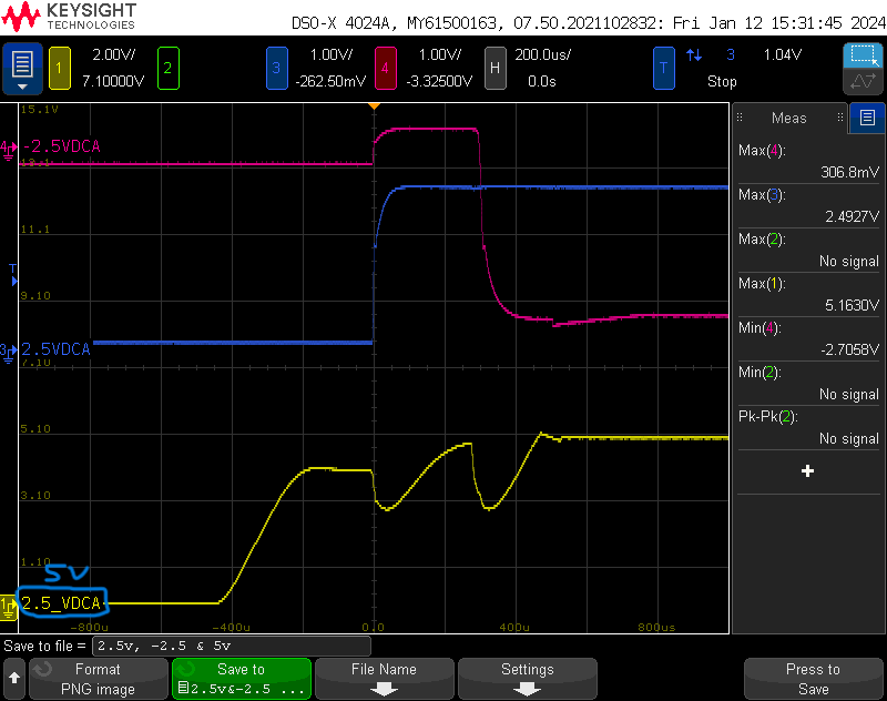
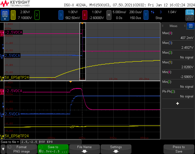
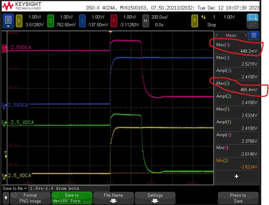
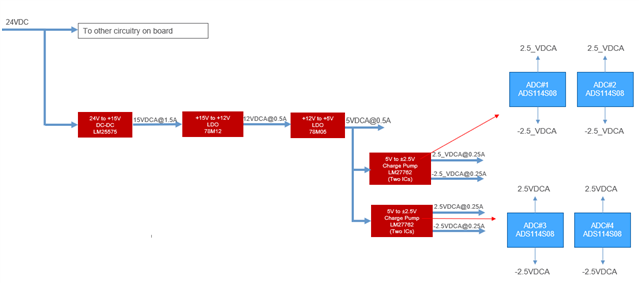
We have observed some startup overshoot on -2.5V power supply connected to the ADC chip ADC114S08. See below waveform and the Power Supply tree. 

This overshoot is not present when ADC power supply is disconnected from the charge pump output.

Can you please let us know what could be the reason for this overshoot and whether this is critical for ADC114S08 operation? How to prevent this? FYI, So fare we have not seen any failures or any ADC operation issues.

Appreciate if you could measure this on any of ADC114S08 evaluation board powered from bipolar supply and confirm its behaviour if it is related to our circuitry or it is inherit property of ADC114S08.

Let me know if you need any additional info.

Also let me know how I can raise this as a ticket to TI FAE instead of discussing it on TI forum. 

Thanks.

  • Hi,

    Please allow us some time to respond as many of our engineers are out for the holidays. Thank you. 

  • Hi Kamalnish Arora,

    If you power the LM27762s directly with a lab supply, do you still see the glitching? In other words, can you remove / disconnect the 78M05 and connect the input of the LM27762 to a +5V lab supply? Reading through your other post about the LM25575 it appears that there could have been a current limit issue.

    Can you also provide a schematic of your system, including the ADC and the power supplies?

    -Bryan

  • Thanks for your reply Bryan.

    I remember I removed the 78M05 and capturted the input glitch and it did show some improvement on the startup glitch, but did not power the 5V circuitry from lab PS after removing 78M05 and also did not capture the +/-2.5V rails.   

    I got stuck in some high priority stuff, will get back to you soon after taking scope captures.

    Regards,

    Kamalnish

  • Hi Kamalnish Arora,

    Thanks for the update, let us know when you have more info

    -Bryan

  • Hi Bryan,

    I captured the +/-2.5V rails after removing the 78M05 and powering the 5V board ciruitry from external PS. Refer below scope waveforms before and after removing of the 78M05. Looks like it is not the current limit issue. I am curious to understand what is causing the some startup overshoot on -2.5V power supply connected to the ADC chip ADC114S08?

    Appreciate if you could measure this on any of ADC114S08 evaluation board powered from bipolar supply and confirm the startup Power supply behaviour  of ADC114S08.

    I am also attaching the ADC and PS schematic for your reference.

    ADC and PS Sch for TI.pdf

    Regards,

    Kamalnish

  • Hi Kamalnish Arora,

    What happens if you bypass the LDOs and directly power the ADC with +/-2.5V using the lab supply? Do you still see this issue? The ADS114S08EVM is not setup to accept bipolar supplies, so I am not able to test this specific behavior at this time. However, we have other customers using the ADC with bipolar supplies and I have never see this issue before.

    In the second scope shot you sent, is that with the 78M05's removed completely? Do you know why it is taking so long for the 5V supply to ramp (~30-40ms)? This ramp did not occur with the 78M05's installed. Are you measuring that at the output of the power supply, or somewhere on the board? If on the board, where? Does the power supply have a current limit?

    -Bryan

  • Hi Bryan, 

    It is very difficult to bypass the charge pump and directy power the ADC with +/-2.5V as +/-2.5V is connected through power planes on our board. That's why I was requesting to check on any EVM pr any other TI board where the bipolar power supplies are in use. 

    Regarding your second point, Yes, 78M05 was removed completely and I connected input power directly to the output of 78M05 TP close to the o/p cap C232. It looks to me the external Power supply has Turn-On rise time (soft start) of about 30-40ms and there is no soft start control on 78M05 thats why you see ramp with external PS. I used the Keysight U8002A 0-30V/5A adjustable Power supply at full current limit of 5A @5V output. 

    Regards,

    Kamalnish

  • Hi Kamalnish Arora,

    Thanks for getting back to me, let me look at this in more detail tomorrow

    -Bryan

  • Hi Kamalnish Arora,

    I was able to look at this issue today. As mentioned, I could not replicate the behavior on the ADS114S08 EVM because the EVM is not setup to use bipolar supplies. However, the ADS1261 EVM is, and it just so happens to have an LM27762 on it to generate +/-2.5V supplies

    I was able to see similar startup behavior as you showed in your system. See the first scope image below

    In the second image, I bypassed the LM27762 and powered the ADC directly from my lab power supply. As you can see, there is no strange startup behavior, so this is an interaction between the LM27762 and the ADC.

    The LM27762 basically has a delay where the positive supply has to ramp before the negative supply, because the positive supply is used to generate the negative supply. This is evident from the behavior we both saw (the first scope shot). During this time, the negative LDO output is effectively floating. Internally, the ADC AVDD supply starts pulling AVSS higher, because AVDD (LDO positive output) is being driven while AVSS (negative LDO output) is not. Once AVSS passes the threshold specified in the absolute maximum ratings (0.3V with respect to DGND), the ADC internal ESD diodes turn in to help protect the device. Since the voltage is not rising dramatically beyond 0.3V (I think you saw about 0.45V in your measurements), this likely means that you are not drawing a lot of current through the ADC ESD cells and the ADC is unlikely to be damaged. If you want to know for sure, you can place a small-ohm e.g. 5 ohm, resistor in series with AVDD and measure the current during startup using your scope.

    Then, if you want to try to divert this "fault" path out of the ADC, place a Schottky diode between AVSS and DGND. I saw that you tried this previously and it reduced the max voltage from 0.45V to 0.35V, or approximately the diode forward voltage drop. This likely indicates that the current was being shunted through the external diode as opposed to the ADC's internal ESD diode, which is what you want. If you can find a diode with a forward voltage drop <0.3V, that would most likely keep the ADC ESD diode from even turning on, which is the desired behavior

    -Bryan

  • Thanks Bryan for confirming the behaviour from the EVM and I agree it is because of the interaction between the Charge Pump LM27762 and the ADC ADS114S08. 

    Do you recommend we keep the design as it is without adding any Diodes or we should add the Diodes? For adding the Diodes we need to change the PCB layout. If you are recommending Diode, appreciate if you can you suggest 1 or 2 part numbers suitable for this. I found PMEG2010ER with very low forward voltage Vf<0.3V @0.1A from 0-70C range.

    Regards,

    Kamalnish

  • Hi Kamalnish Arora,

    Our official recommendation is to not violate the ADC absolute maximum ratings. You could use two separate LDOs to eliminate the delay between LDO+ and LDO- turning on with the LM27762 solution. While this is not an ideal solution, the behavior would look more like the second scope shot I sent in my last post.

    A diode could be an alternative solution to limit the voltage increase before LDO- turns on. I don't have a specific diode to recommend for this application, but I think a quick Digikey search using the parameters you identified would be sufficient to find a suitable device. The PME device you called out could work, though I would try any diode in your system first before spinning the board

    -Bryan

  • Thanks Bryan, I will try putting clamping Diodes first and see if it improves. 

  • Hi Kamalnish Arora,

    I am glad we could help

    -Bryan

  • Hi Bryan,

    I tested my board after putting low Vf diodes and it resolved the issue.

    Thanks for your support.

    Regards,

    Kamalnish