This thread has been locked.

If you have a related question, please click the "Ask a related question" button in the top right corner. The newly created question will be automatically linked to this question.

ADC3683: output bit fromat

Part Number: ADC3683

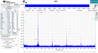
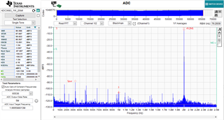
Due to clock distribution constrains in my design I would like utilize 20-bit output formatting in all modes: By-pass, real, complex (NCO is active). 1 wire connection is preferred. Acc. the datasheet is possible, but evaluation SW ADC35xx_EVM_GUI offers only 14, 16 and 18 bit formats. Are there any limitations for 20-bit output format?

  • Hi Viktor,

    I will need to verify this before confirming anything. This could take me until early next week. I have also attached the SPI writes for 20-bit output interface in a text file. It includes the necessary SPI writes to bring up the part in 20-bit output mode. The only thing I did not include is any SPI writes for decimation configuration.

    If the file doesn't make sense feel free to reach back out with any questions.

    Best regards,

    Drew

    20-bit_Configs.txt
    Fullscreen
    1
    2
    3
    4
    5
    6
    7
    8
    9
    10
    11
    12
    13
    14
    15
    16
    17
    18
    19
    //Reg Data
    //2 wire bypass
    0x00 0x01
    0x00 0x00
    0x07 0x4B
    0x13 0x01
    0x13 0x00
    0x19 0x10
    0x1B 0x40
    //2 wire real
    0x00 0x01
    0x00 0x00
    0x07 0x4B
    0x13 0x01
    0x13 0x00
    0x19 0x10
    0x1B 0x40
    XXXXXXXXXXXXXXXXXXXXXXXXXXXXXXXXXXXXXXXXXXXXXXXXXX

  • Hi Viktor,

    Is there a specific input clock speed and input frequency you are interested in? If so, I can use those when I look at this. Otherwise I will be using the max clock rate of 65 MSPS.

    Best regards,

    Drew

  • Thank you for excellent detailed answer. The sample clock is 61.44MHz. 2 wire connection I don't want to use, thus register setting need not to be attached. NCO frequency in the complex mode is fixed = 7.8MHz. 

  • Hi Viktor,

    Yea I missed the line about 1-wire preferred. Thank you for the quick response. What input frequency are you using for bypass, real decimation, and complex decimation (sssuming 7.8 MHz is just the NCO value and not expected output frequency after shifting)? What decimation factor are you using?

    Best regards,

    Drew

  • Input frequencies
    Bypass: DC...20MHz (one ADC channel), no decimation
    Real: DC...10MHz (one ADC channel), decimation = 2
    Complex: center freq = 7.8MHz and with decimation factors = 4 or 8 or 32

    In principle I just need to verify if 20-bit output format is allowed to use for all settings mentioned above. 

  • Hi Viktor,

    Yes, 20 bit output is available in the setting you have mentioned.

    Here is a bypass data capture:

    Here is a real 2x decimation capture

    I was able to get data captures in complex mode but am not exactly sure of the specific conditions you mentioned. But the part does work for 20 bit output mode using complex decimation.

    Best regards,

    Drew