This thread has been locked.

If you have a related question, please click the "Ask a related question" button in the top right corner. The newly created question will be automatically linked to this question.

ADS131E08: ADS131E offset and weird Internal reference

Part Number: ADS131E08
Other Parts Discussed in Thread: THS4561

Good Morning!!

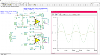
I have configured the CONFIG3 register of my ADS131E08 as 0xE0 (opamp off, internal reference 4V).

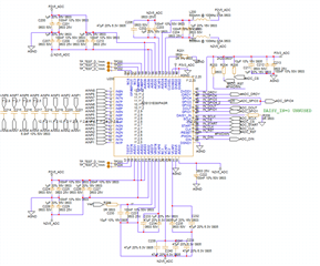
Before of the ADC I have a 2nd order LP Butterworth filter.

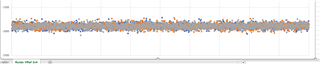
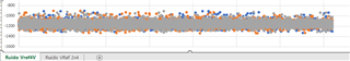
Se measure of the ADC has an offset that I cant see with my oscilloscope and Checking the VREFP-VREFN value with an multimeter I realized that le internal Vref is 4.983V and I dont understand why.

Also I am trying to do the conversion of the data to volts with FS*data/2^23 and the value obtained is far of the expected.

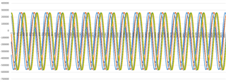
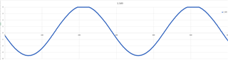
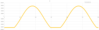
These curves represent the output of the ADC with the same input trying to get the best VCAP values, The input has no offset, the oscilloscope measure has no offset, but the data sent by the ADC has a big negative offset.

AVSS is conected to -2.5V and VREFN is joined to this point, VREFP is conected to two capacitors as indicated in the datasheet.

  • Hi ,

    Welcome to TI E2E forum. 

    Can you please share your schematic? Did each channel show the same behavior?

    I would suggest you to do one more test: short ADC's input internally by programing CHnSET registers to set MUXn[2:0] to 001. Please let me know the result.

    Regards,

    Dale

  • My VREFP voltage is 1.5V and my VREFN=AVSS=-2.5V so (VREFP+VREFN)/2 = -0.5V. Is it the reason why I am seeing a negative offset?

    Im trying diferent filters configuration, so I have diferents offset values but all thee empty inputs have negative values.

    On monday I wil change.

    This same schematic is working in other PCBs but configuring Vref internally to 2.4V.

    Many VCAP capacitors are unmounted in oprder to match with the datasheet expects, and the resistor R209 which connect external Vref.

  • I made the test suggested:

    How can I fix the Vcm to 0V. can there be a symmetry problem in the +-2v5 power supplies?

  • Hi Alberto Sanchez Garcia,

    Dale is out of the office for the next few days, we will get back to you by the end of the week. Thanks for your patience

    -Bryan

  • Hi Alberto Sanchez Garcia,

    Thanks for your patience. 

    Your reference voltage is correct, the reference voltage (Vref) is the voltage difference between VREFP and VREN, so Vref = (VREFP – VREFN) =1.5V-(-2.5V)=4V.

    I believe your VREFP has a stable 1.5V according to your last measurement for shorted input I suggested, your measured result shows a -1200 code (approximate mean value) for 4V Vref, this code is around 572uV if you convert it to a voltage, This is actually reasonable offset error for this ADC. If you expect to see 0V for shorted input, you will have to do an offset calibration. You can check the details about ADC offset calibration in other threads on this E2E forum or watch the video Understanding and calibrating the offset and gain for ADC systems of TI's Precision Labs ADC series.

    If you see a much higher error code for your own analog input signal (e.g. the sinewave you showed, I can not see the details from your image), that error should come from your front-end circuit including your filter. You might have to check the signal on ADC's analog input pins with an oscilloscope.

    If the voltage you measured on VREFP is not a stable 1.5V as expected, probably your reference is oscillating, I would suggest you to check if the capacitors you soldered between REFP and REFN have correct recommended values, and also make sure C233, C232, C206 are not installed. Also, the ADS131E08 datasheet recommend "Connect a 22-µF capacitor to AVSS" for VCAP1 pin, but your schematic shows 4*47uF capacitors in parallel with VCAP1, please double check as well. The ferrite bead L202 is not recommended for ground connection, AVSS4 pin should be directly tied to your N2V5 negative power supply.

    Regards,

    Dale

  • Hi Dale, thank you very much for your answer. I´ve injected directly in the ADC sine waves and I realized there is no offset. The offser appears when i inject it before de Butterworth filter.

    I got a 400mV offser with 4Vref and 2.4Vref:

    Do you have any clue about what is wrong in my schematic?

    The TINA simulation shows a perfect wave, and with the oscilloscpe probe the offset didn´t appear. I just see it it the ADC readings...

    Thank you so much for your time.

  • Hi Alberto Sanchez Garcia,

    THS4561 is supported by another team at TI, you can post your query in the Amplifier forum to get the best support. 

    Regards,

    Dale