This thread has been locked.

If you have a related question, please click the "Ask a related question" button in the top right corner. The newly created question will be automatically linked to this question.

ADS1263: can not read data via SPI using STM32 controller

Part Number: ADS1263
Other Parts Discussed in Thread: ADCPRO

Hi,

    as usual - the new ADC - the new connectivity issues.
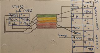
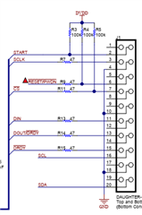
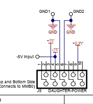
    So, I have STM32F427 controller and I want to get data from ADC ADS1263 via SPI5 port .

    I have used ADCPro and able to read ADC data successfully under ADC on PC.
    For STM32 case I decided to use the simplest setup (positive active serial data, data active on falling edge, but 16-bit SPI word):
    (I also checked simple SPI loop-back - shorting MOSI and MISO - this works ok.)
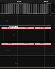
     Write Reset (06h) command to ADC
     Write Read Register #0 (20h 00h)
     read data from register #0 - 16 bit
     Write Start ADC1 conversions (08h)
     all this is rendered on pic #1

     Read Register command (2000h) looks unsuccessful, as I can not see ADC ID from register #0. Ok.     
     
     
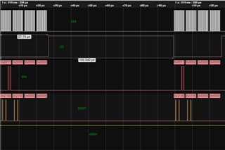
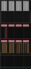
     After initialization I try to read data from ADC via writing 16-bit command "Start conversion" 0x0012h. This is rendered on pic #2.
     And further - I'm reading 3 x 16bit words. And I always read 210000h.
     So, as I'm not sure if Read Register command works well, I'm not sure ADC readings are meaningful.
     
     Anyway, previously I was able to use this SPI5 port for 16-bit word exchange, so looks like I do something wrong. Please suggest me where I'm wrong.


  • Hi Dmytro Rahozin,

    Do you have a custom board that you designed or are you using the ADS1263 EVM and fly wiring to an STM breakout board? If you are fly-wiring the board, can you please send a picture of how the two boards are connected? Please send detailed high resolution images so I can clearly see how the wires are connected, etc.

    -Bryan

  • Thank you!
          This is the "scheme" for connecting J1 slot and a slot on our board.
      

     There is also J5 "power" slot, here I connected only pins 5 and 6 for ground and pin 3 +5V. I have not connected pin 9 "+3.3V", I believe it is not used.

  • Hi Dmytro Rahozin,

    Thanks for sending these images. Can you send me pictures of your actual physical board, instead of just a connection diagram? It is possible that there are discrepancies between your diagram and the actual board. I would also like to see how the power and ground connections are made

    -Bryan

  • Thanks, I have got replays from ADC
    I have not noticed, that external +3.3Volts supply pull-up resistors for START, -RESET and -CS pins. START was tied to ground, -CS was controlled by STM32, but -RESET was not connected (I had in mind it has pull-up) and w/o 3.3V it was it zero, so ADC was in shut down mode.
    Now I have better picture and will continue my "pursuit" to get data at ~10kHz rate.

  • Hi Dmytro Rahozin,

    Thanks for the update, this is why I wanted to see how the board was physically connected, not just the connection diagram. It is important to see how all of the ADC pins are biased / connected to be able to determine how the device with behave.

    -Bryan

  • Sure. I believe in the nearest future I'll have another question on how to wire my sensors properly to ADS1263. :)