Other Parts Discussed in Thread: ADS7038
Hi,
In the datasheet of ADS7038-Q1, the behavior of GPI/GPO in Manual mode is not mentioned clearly. Can you please support on what will be the output behavior in the following scenario ?
| CH_ID | Pin configuration | Tx in Manual Mode | Output Behaviour? (Rx frame) |
| 0 | AN0 | Send request to read the CH_ID 0's ADC value in Manual mode in address 0x11 -> MANUAL_CH_SEL Switch to AIN0 |
|
| 1 | AN1 | Send request to read the CH_ID 1's ADC value in Manual mode in address 0x11 -> MANUAL_CH_SEL Switch to AIN1 |
|
| 2 | Digital I/P | Read value from GPI_VALUE register | Which data is received in the Rx frame ? AN0's value or Digital I/P value of Channel 2 ? |
| 3 | AN3 | Send request to read the CH_ID 1's ADC value in Manual mode in address 0x11 -> MANUAL_CH_SEL Switch to AIN1 |
Will we get value of AN1 in this N+2 iteration ? |
| 4 | Digital O/P | Write Digital HIGH to Channel 4 | Will the Channel become high in this iteration itself ? |
| 5 | Digital I/P | Read value from GPI_VALUE register |
Will we get the I/P value of GPI Channel 5 in this iteration itself ? What happens to the AN3 Value which we are supposed to receive in this N+2 ? |
| 6 | AN6 | Send request to read the CH_ID 6's ADC value in Manual mode in address 0x11 -> MANUAL_CH_SEL Switch to AIN1 |
|
| 7 | AN7 | Send request to read the CH_ID 7's ADC value in Manual mode in address 0x11 -> MANUAL_CH_SEL Switch to AIN1 |
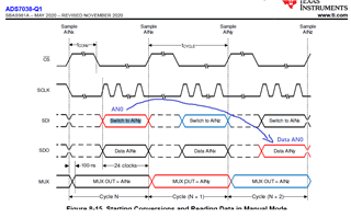
Referred the following diagram in User Manual