This thread has been locked.
If you have a related question, please click the "Ask a related question" button in the top right corner. The newly created question will be automatically linked to this question.
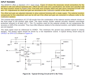
On sheet 13 of the datasheet in the "INPUT RANGES" section, the following text appears - "Figure 24 shows the necessary circuit connections for the ADS8515 with and without hardware trim." However, I believe this should be a reference to Figure 25. Then the following sentence states "Offset and full-scale error specifications are tested and specified with the fixed resistors shown in Figure 25(b)." However, this is confusing because there are no resistors shown in 25(b) and in fact 25(b) is titled "+/-10V Without Hardware Trim". Should this sentence be referencing 25(a)? And if that is the case, then is the sentence stating that the offset and full-scale error specifications are tested and specified with just the fixed resistors shown since the figure also includes a potentiometer? I'm assuming "fixed resistors" refers to the 20KOhm, 30KOhm, and 175KOhm value and to further improve on the offset and full-scale error specifications, a potentiometer can be used to calibrate the system by fine tuning the 20KOhm resistor value. Please confirm. Thank you
Hi Shane,
Thank you for your post. I'm looking into this and will get back to you with a reply tomorrow.
Regards,
Ryan
Hi Shane,
Thank you for sharing this feedback. I think the highlighted text below could be completely moved to the Calibration section of the data sheet. Where you see reference to external hardware trim resistors, the correct figure to reference is 25(a). Even though it says "fixed resistors," I would assume the "potentiometer" is shown to indicate where to vary the resistance for gain error calibration. A potentiometer may not be required in the final design.
For future reference, you can always submit document feedback using this link below. We can certainly help to clarify questions via the forum, but our systems team uses the logged feedback whenever they go back and revise datasheets.
Regards,
Ryan
Thank you for the response, Ryan. Unfortunately for my application, software calibration and hardware trimming on every unit using a potentiometer won't be viable options. The specifications shown in the datasheet for the full-scale error and bipolar zero error would meet our performance criteria. Per note (3) on page 3, the indication is that the values listed for these parameters are measured using the schematic showing the fixed resistors, but again there isn't necessarily a schematic showing only fixed resistors unless we assume the 20 KOhm potentiometer shown in figure 25(a) could be a fixed resistor. (Also note 3 references Figure 22 but this should be Figure 25). My hope is that the specifications listed can be obtained using only fixed resistors, and I was hoping for confirmation that this is true before we start our prototyping efforts.
Thanks again
Hi Shane,
Would it be possible to calibrate your system by trial and error during the prototype phase, adjusting the fixed resistor values until the best combination is achieved? A potentiometer is not a requirement for this method, just more practical to vary the resistor ratio and scale the voltage connected to the REF pin.
And thanks for the feedback on the footnote on page 3. I'll also include this in the data sheet feedback submission.
Regards,
Ryan
We can certainly calibrate during the prototyping phase but my concern would be the variation from device to device, or between lots. A specific combination that works on the prototype unit may not be viable on all the production units, for example.