- Ask a related questionWhat is a related question?A related question is a question created from another question. When the related question is created, it will be automatically linked to the original question.
This thread has been locked.
If you have a related question, please click the "Ask a related question" button in the top right corner. The newly created question will be automatically linked to this question.
We are using an ADC chip ADS1256 in our product, and now we have found an issue happened to about 10% of our prototypes, as described below:
In order to get good linearity, we used the 'buffer on' function inside the chip. For the issue prototypes, when the input voltage exceeds AVDD - 2 V, the ADC output will fiercely drop and then lock up.
For example, the power supply is 5V,
When the input is 3V, the reading is ~ 5100000
When the input signal rises to 3.7V, the reading is ~ 6260000
When the input signal rises to 3.8V, the reading is ~ 3230000
When the input signal rises to 4V, the reading is ~ 3230000
For higher input voltages, the ADC reading is kept near 3230000, with little change.
This phenomenon only occurs on ~10% prototypes. For the rest prototypes, when the input exceeds 3.7V, the ADC reading will be kept as the saturated reading as ~6400000.
We have two questions:
1. Is there a way, such as some special registers configuration, to ensure that the ADC output saturated value when input voltage exceeds the threshold and 'buffer on' is enable?
2. For those ADCs that do not have this issue in our factory now, will this problem occur on the client side due to environmental factors and aging after leaving the factory?
Thank you very much!
Hi Derek Yang,
Operating at an input voltage >3V with the buffer enabled is outside of the ADS1256 recommended operating conditions, according to the datasheet. The behavior of the ADC is undefined at this point, so there are no guarantees or suggestions we can make if you are operating the device in this manner, other than to say "don't operate the ADC in this manner".
-Bryan
Thanks for your reply Bryan. I am afraid I cannot fully agree your point.
In ADS1256 datasheet, the detail description of buffer on is:
"With the buffer enabled, the voltage on the analog inputs with respect to ground (listed in the Electrical Characteristics as Absolute Input Voltage) must remain between AGND and AVDD − 2.0V. Exceeding this range reduces performance, in particular the linearity of the ADS1255/6. "
My understanding is, if the input voltage > 3V, the ADC readings will lose accuracy and linearity, and it may be saturated at some voltage and reduce the dynamic range. However, I don't think it makes any sense that the ADC reading loses its monotonicity and suddenly drop to half, especially considering that the input (such as 3.9V) is much less than the absolute max rating value (6V).
I have used ADS1256 for several years. Maybe I am lucky, and this is the first time I met this losing monotonicity issue. Actually, this is the 1st time for all the ADC chips I have used to lose monotonicity and drop to half value.
Other than simply say 'don't operate the ADC in this manner', I think at least Ti can modify the datasheet, more specificly tell the customers the failure mode, or perform better factory test and avoid this phenomenon. Considering ADS1256 is a very old chip, maybe TI can start to develop a replacement chip.
How do you think?
Hi Derek Yang,
If I understand the problem statement correctly: you have been using the ADS1256 for many years, and during that time you have used those devices in this same manner (overranging the inputs to >AVDD-2V when the buffer is enabled). Until recently, those "older" devices had an approximately monotonic response to the applied input voltage, even when the inputs were overranged to >AVDD-2V when the buffer was enabled. Now, approximately 10% of your "newer" devices exhibit a different behavior, where at some point during the overrange there is a code shift such that the output is reduced by 1/2 and then stays at that code, regardless of changes in the ADC input. Is that correct?
Also:
There is a next generation version of the ADS1256, which is the ADS1261.
-Bryan
Hi Bryan,
yes, your description is right.
Hi Derek Yang,
Thanks for confirming.
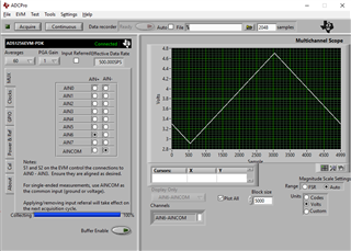
I checked this out on my ADS1256EVM, see the results below. I was inputting a very slow moving (0.1 Hz) triangle signal to mimic your input signal increasing beyond 3V (2.9V to 4.7V, at a DC offset of 3.8V to be precise). You can see how the ADC converted this signal with the buffer off in the first image.
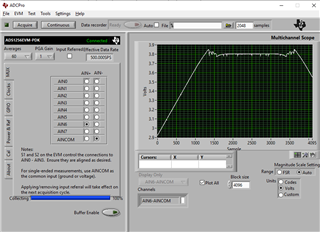
In the second image the only difference is that the buffer is on. Note how the device clips the output code at approximately 3.8V, which mirrors your results
I spoke with one of our designers and they mentioned that it is possible for the buffer + startup circuit to clip at a lower voltage / output code once the buffer circuit current drops to 0 (around the 3.8V point), so the behavior you are seeing, while uncommon, is not impossible. The fact that the device recovers in either case means that this circuit is operating as it was designed, albeit with different intermediate behavior compared to what you were expecting.
There is no way for TI to guarantee that you will see consistent behavior outside of the recommended operating conditions (ROC), this is just not something we look for. The whole purpose of the ROC is to bound the conditions we need to test for in production and then guarantee reliable operation to the end user. It would be an endless effort to then also investigate every other combination of conditions that could potentially lead to uncertain behavior outside of the ROC.
So, my original recommendation stands: if you want to avoid this behavior all together, do not operate the ADC in this manner. I am not sure what value this information could provide to your system's end user as the behavior is not well defined at VIN > AVDD-2V with the buffer enabled
Buffer off

Buffer on

-Bryan
Hi Bryan,
Thank you very much for all you have done!
We have changeed the firmware and set 'buffer off' to solve this problem. And now the system is under testing.
The failure mode of my system is, if this issue happens, when a half saturation value is read out, the system will treat it as 1.9V even if it may be 4.5V. Then the system will control power as 1.9V and the whole system will act abnormal.
My understanding is silicon based product should be very stable. If the ADC chip behaves correctly in our factory, it will keep behaving well in field. If so, I can sort in our factory as a short term solution before firmware is fully tested. How do you think?
Best regards,
Derek