Hii,
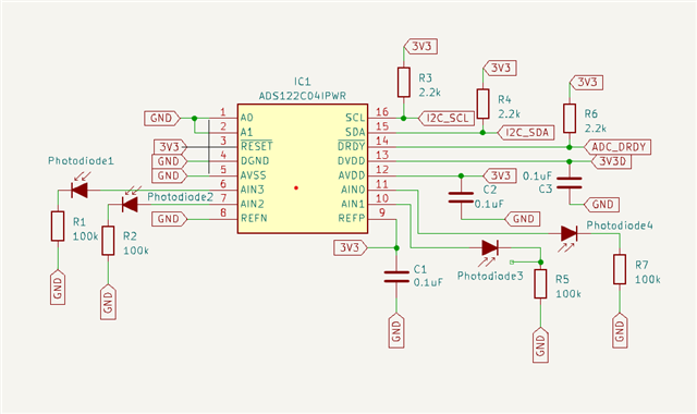
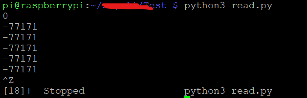
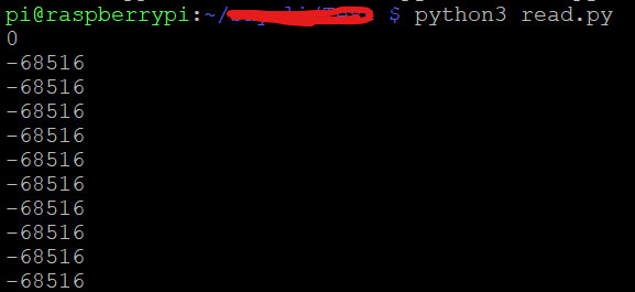
I am trying to read photodiode value using ADS122C04 using raspberry pi4 with i2c.But i am getting constant output as change in input(Photodiode value).
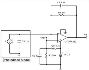
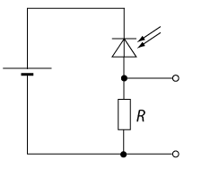
Please correct me if any change in circuit i am using following circuit..
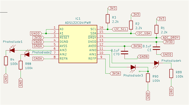
The following is the library for ADS122C04 i am using
import RPi.GPIO as GPIO
from time import sleep
from smbus2 import SMBus, i2c_msg

class ADS122C04:
    CMD_RESET               = 0x06
    CMD_START_SYNC          = 0x08
    CMD_POWERDOWN           = 0x02
    CMD_RDATA               = 0x10
    CMD_RREG                = 0x20
    CMD_WREG                = 0x40

    MUX_MASK                = 0x1F
    MUX_DIF_0_1             = 0x00
    MUX_DIF_0_2             = 0x10
    MUX_DIF_0_3             = 0x20
    MUX_DIF_1_0             = 0x30
    MUX_DIF_1_2             = 0x40
    MUX_DIF_1_3             = 0x50
    MUX_DIF_2_3             = 0x60
    MUX_DIF_3_2             = 0x70
    MUX_SINGLE_0            = 0x80
    MUX_SINGLE_1            = 0x90
    MUX_SINGLE_2            = 0xa0
    MUX_SINGLE_3            = 0xb0
    MUX_REFPmREFN           = 0xc0
    MUX_AVDDmAVSS           = 0xd0
    MUX_SHORTED             = 0xe0

    GAIN_MASK               = 0xF3
    GAIN_1                  = 0x00
    GAIN_2                  = 0x10
    GAIN_4                  = 0x20
    GAIN_8                  = 0x30
    GAIN_16                 = 0x40
    GAIN_32                 = 0x50
    GAIN_64                 = 0x60
    GAIN_128                = 0x70

    PGA_DISABLED            = 0x1
    PGA_ENABLED             = 0x0

    DATA_RATE_MASK          = 0xF3
    DATA_RATE_20SPS         = 0x00
    DATA_RATE_45SPS         = 0x10
    DATA_RATE_90SPS         = 0x20
    DATA_RATE_175SPS        = 0x30
    DATA_RATE_330SPS        = 0x40
    DATA_RATE_600SPS        = 0x50
    DATA_RATE_1000SPS       = 0x60

    OP_MODE_NORMAL          = 0x00
    OP_MODE_TURBO           = 0x10

    MODE_MASK               = 0xFD
    MODE_SINGLESHOT         = 0x00
    MODE_CONTINUOUS         = 0x02

    VREF_INTERNAL           = 0x00
    VREF_EXTERNAL           = 0x10
    VREF_AVDD               = 0x20

    ### TEMP SENSOR MODE
    TEMP_SENSOR_OFF         = 0x00
    TEMP_SENSOR_ON          = 0x10

    #### --- Configuration Register 2
    ### DATA COUNTER ENABLE
    DCNT_DISABLE            = 0x00
    DCNT_ENABLE             = 0x10

    ### DATA INTEGRITY CHECK
    CRC_DISABLED            = 0x00
    CRC_INVERTED            = 0x10
    CRC_CRC16_ENABLED       = 0x20

    ### BURNOUT CURRENT SOURCE
    BURN_OUT_CURRENT_OFF    = 0x00
    BURN_OUT_CURRENT_ON     = 0x10

    ### IDAC CURRENT SETTING
    IDAC_CURRENT_OFF        = 0x00
    IDAC_CURRENT_10_UA      = 0x10
    IDAC_CURRENT_50_UA      = 0x20
    IDAC_CURRENT_100_UA     = 0x30
    IDAC_CURRENT_250_UA     = 0x40
    IDAC_CURRENT_500_UA     = 0x50
    IDAC_CURRENT_1000_UA    = 0x60
    IDAC_CURRENT_1500_UA    = 0x70

    #### --- Configuration Register 3
    ### IDAC1 ROUTING CONFIGURATION
    IDAC1_DISABLED          = 0x00
    IDAC1_AIN0              = 0x10
    IDAC1_AIN1              = 0x20
    IDAC1_AIN2              = 0x30
    IDAC1_AIN3              = 0x40
    IDAC1_REFP              = 0x50
    IDAC1_REFN              = 0x60

    ### IDAC2 ROUTING CONFIGURATION
    IDAC2_DISABLED          = 0x00
    IDAC2_AIN0              = 0x10
    IDAC2_AIN1              = 0x20
    IDAC2_AIN2              = 0x30
    IDAC2_AIN3              = 0x40
    IDAC2_REFP              = 0x50
    IDAC2_REFN              = 0x60


    def write_command(self, reg, cmd):
        write_command = 0x40 | (reg << 2)
        self.bus.write_byte(self.i2c_adr, write_command, cmd)

    def send_command(self, cmd):
        self.bus.write_byte(self.i2c_adr, cmd)

    def read_registers(self, reg, size):
        write = i2c_msg.write(self.i2c_adr, [reg])
        read = i2c_msg.read(self.i2c_adr, size)
        self.bus.i2c_rdwr(write, read)
        return list(read)

    def send_command(self, cmd):
        self.bus.write_byte(self.i2c_adr, cmd)

    def start(self):
        self.send_command(0x08)

    def reset(self):
        self.send_command(0x06)

    def powerdown(self):
        self.write_command(self.CMD_POWERDOWN)

    def config(self, mux=MUX_SINGLE_2, gain=GAIN_1, datarate=DATA_RATE_90SPS, mode=MODE_CONTINUOUS, ref=VREF_EXTERNAL, pga=PGA_DISABLED, op_mode=OP_MODE_NORMAL, temp=TEMP_SENSOR_OFF, dcount=DCNT_DISABLE, crc=CRC_DISABLED, bcurrent=BURN_OUT_CURRENT_OFF, idac=IDAC_CURRENT_OFF, idac1=IDAC1_DISABLED, idac2=IDAC2_DISABLED):
        value = mux | gain | datarate | mode | ref | pga | op_mode | temp | dcount | crc | bcurrent | idac | idac1 | idac2
        self.bus.write_byte_data(self.i2c_adr, self.CMD_WREG, value)

    def ready(self):
        buffer = self.read_registers(self.CMD_RREG | 4, 1)
        return buffer[0] & 0x80

    def waitForResult(self):
        if self.rdyPin > 0:
            GPIO.wait_for_edge(self.rdyPin, GPIO.FALLING)
        else:
            while not self.ready():
                sleep(0.0005)

    def result(self):
        buffer = self.read_registers(self.CMD_RDATA, 3)
        value = (buffer[0] << 16) | (buffer[1] << 8) | (buffer[2])
        if value >= 0x800000:
            value = value - 0x1000000
        return value

    def callback(self, callbackFunction):
        GPIO.add_event_detect(self.rdyPin, GPIO.FALLING, callback=lambda _: callbackFunction())

    def __init__(self, port=1, address=0x45, rdyPin=0):
        # print("_INIT_")
        self.i2c_adr = address  # 0x40
        self.bus = SMBus(port, True)
        self.rdyPin = rdyPin
        if rdyPin > 0:
            GPIO.setmode(GPIO.BCM)
            GPIO.setup(rdyPin, GPIO.IN)

    def __enter__(self):
        # print("_ENTER_")
        return self

    def __del__(self):
        # print("_DEL_")
        self.bus.close()

    def __exit__(self, exc_type, exc_value, traceback):
        # print("_EXIT_")
        self.bus.close()
This is code i am using
from time import sleep
from ADS122C04_lib import ADS122C04

ads=ADS122C04( rdyPin=4 )

ads.reset()
ads.config(ads.MUX_SINGLE_2, ads.GAIN_1, ads.DATA_RATE_90SPS, ads.MODE_CONTINUOUS, ads.VREF_EXTERNAL, ads.PGA_DISABLED, ads.OP_MODE_NORMAL, ads.TEMP_SENSOR_OFF, ads.DCNT_DISABLE, ads.CRC_DISABLED, ads.BURN_OUT_CURRENT_OFF, ads.IDAC_CURRENT_OFF, ads.IDAC1_DISABLED, ads.IDAC2_DISABLED)
ads.start()
try:
    while True:
        result = ads.result()
        print(result)
        sleep(1)  # Adjust the sleep duration as needed
except KeyboardInterrupt:
     pass
Please Help
Thanks,