This thread has been locked.

If you have a related question, please click the "Ask a related question" button in the top right corner. The newly created question will be automatically linked to this question.

ADC3683: Power on/reset calibration and datasheet INL test setup

Part Number: ADC3683

We are attempting to improve the INL performance of the ADC3683 by using code correction techniques.  In our measurements we generally see a greater INL magnitude than reported as typical in the ADC3683 datasheet and also variance of at least +/-4 LSB in the INL characteristic between test runs, although at the moment we issue a software reset at the start of each test run. We are using the EVM balun input to generate our INL plots with high order ADC testing filters and sinusoidal excitation.  Sample clock is generated from a high performance clock source.  This has raised a number of questions about the behaviour of the ADC3683.

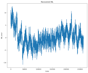
A typical INL result we have measured is:

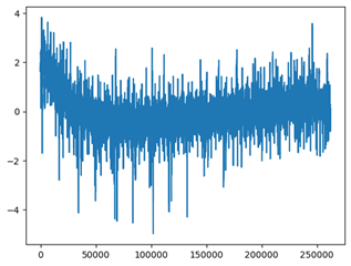
After power cycling though we have the following diff between a new INL measurement and the measurement above:

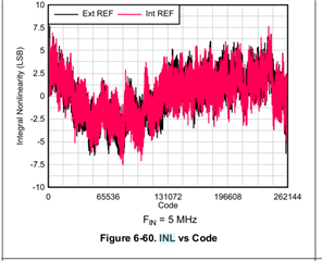
1)   Was this figure on page 24 of the datasheet produced using the EVM circuit (which includes baluns that add some non-linearity) or was a special circuit used?

2)  Is the ADC power up calibration expected to yield the same INL characteristic each startup? (I.E is it deterministic) 

"Apply hardware reset. After hardware reset is released, the default registers are loaded from internal fuses
and the internal power up capacitor calibration is initiated. The calibration takes approximately 200000 clock
cycles." P.G 72 

3) Does a software reset (write to REG 0x0) trigger the calibration routine or is this only triggered by hardware reset?

  • Hi,

    What is the typical INL value that you are observing? Are you writing any registers before you get your typical INL plot? Is the other INL plot coming directly after a power cycle or are there any register writes being performed?

    Can you provide any additional details on how the INL is being captured?

    Best regards,

    Drew

  • The magnitude of the typical INL we observe is ~+/-10 LSB.  

    We provide a sine wave at 942.477796 kHz at +1dBFS and use the cumulative histogram method of Doernberg, Joey et al. “Full-speed testing of A/D converters.” IEEE Journal of Solid-state Circuits 19 (1984): 820-827.  on ~ 1.278e8 samples.  The sine wave is filtered by an ADC testing filter from LC17T-1.25M-50-5294A filter (17 pole Chebyshev low pass 1.25 MHz -3dB).  This sine wave is input to the EVM using the balun path.    

    The ADC is set to 18 bit 2W mode.

    We have done further testing an observed that if the INL test is performed 5 times in succession without power cycle or toggling the reset register (0x0) the INL is stable to within ±1.5 LSB from the mean however if we issue a reset by toggling the reset register the next INL measurement is +/-4LSB from the previous 5 results mean.  

  • Hi,

    How exactly have you configured the device before the first 5 successive tests? Just a hardware reset? Any register writes? I am trying to confirm the exact state of the part before the software reset is given.

    Best regards,

    Drew

  • Hi Drew,  Just looking through the code I have I see some configuration error where the output bit mapping is never set due to an incorrect E-Fuse address.  Currently the code does:

    0x0 <= 1 (if set to reset the device, this line is commented out during the 5 runs I did not rest the device)

    wait 

    0x07 <= 0x2B

    0x07 <= 0x01 (the address is wrong here should be 0x13 for E-Fuse)

    wait

    0x07 <= 0x00

    0x1B <= 0x80

    scanning through the datasheet I can't see what the default output mapping is, presumably "001: 2-wire, 18 and 14-bit" or we would not get valid data.  This code runs at the start of every experimental run.  

  • Hi,

    After changing that address to 0x13 and running the efuse, has that changed anything or are you still seeing the same results?

    Best regards,

    Drew