This thread has been locked.

If you have a related question, please click the "Ask a related question" button in the top right corner. The newly created question will be automatically linked to this question.

ADS1298R: Rapid baseline transients on the signal on ECG applications - is it RLD ?

Part Number: ADS1298R

Dear all, 

I am designing an ECG device which is using metal electrodes (the resistance is much higher than gel electrodes).

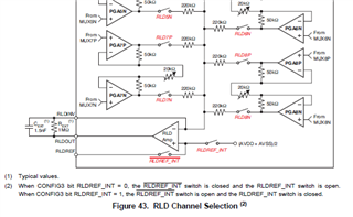
Also, the circuit embeds a defibrillation protection circuit between the electrode and the anti-aliasing filters (see. circuit attached).

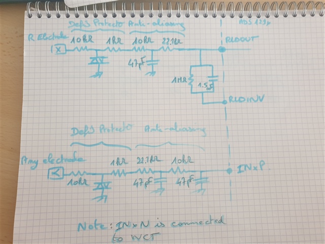
The used values are those from the evaluation board for anti-aliasing filters (two RC filters in a row :10kohm+47pF and 22.1kohm+47pF) and RLD (1Mohm // 1.5nF).

When the contact is getting slightly poorer between the electrode and the patient, the baseline is moving extremely quickly and the ECG becomes uninterpretable.

Please note that the slow baseline drift will be corrected in software and is NOT an issue at all.

I suspect the RLD : do you also share this feeling ? If so, would you decrease the R and/or C value to accelerate the response ? How much ?

Thank you,

Paul-Alexandre,

  • Hello Paul-Alexandre,

    Thank you for your post.

    As you alluded to, the higher electrode impedance makes it difficult ensure the baseline of the ECG signal stays constant enough to allow for baseline wander correction in post-processing. I'm not sure whether the RLD loop response can help much in this case, but it's worth a try. Theoretically, the RLD bandwidth can be increased without much concern - the initial reason for setting the closed-loop bandwidth to ~ 106 Hz was only to ensure amplifier stability while passing the fundamental 50/60 Hz line frequency. Perhaps you can try decreasing Rf to 100 kΩ and then 10 kΩ to increase the bandwidth by 10x and 100x, respectively.

    Are the INxP electrodes selected for RLD common-mode derivation?

    Regards,

    Ryan

  • Dear Ryan

    Thanks for the answer

    I'll give it a try tomorrow 

    Regarding INxP, they are connected to electrodes as in the evalboard

    INxN are mostly connected to WCT apart from those who generate Lead I and Lead II.

    I suppose you refer to Figures 94 and 95 when you say "Are the INxP electrodes selected for RLD common-mode derivation?"

    Common-mode is set using RL electrode so no INxP electrode is selected for Common-mode derivation.

    Thank you

    Paul-Alexandre 

  • Hi Paul-Alexandre,

    I was referring to Figure 43. This is where the input electrodes are connected to the RLD amplifier inverting input through a summing network. This allows the RLD amplifier to drive a common-mode cancellation signal back to the body. The RLD output would still contain the DC bias voltage present on the non-inverting input.

    Let me know how the testing goes!

    Regards,

    Ryan