Hello,
We are currently working with the ADS1298 chip for our ECG application and have encountered a recurring issue related to RLD which makes the tests fail randomly.
We tested for this issue extensively and eliminated most of the common issues like (dry skin, connection issues, revers lead issues, cable issues, muscle noise issue, movement issue).
We suspect that something is not working properly with the ads1298.
Checking the forum we found that similar or same issues ware reported(impedance imbalances on the RLD, high noise, RLD does not properly reduce the noise), but no real solution provided for the ADS1298.
references:
Please help.
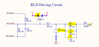
For reference, I have attached the ECG schematics and code.
ads config.txt
 // CONFIG 1
 ads129x_device.base->setReadbackMode(ADS1X_READBACK_DAISY_CHAIN);
 ads129x_device.base->setDataRate(ADS1x_DR2);                        /* SET the output data rate on 4kHz for the DEFAULT LOW-POWER mode */

 // CONFIG 3
 ads129x_device.base->setPowerDownReferenceBuffer(ADS1x_PD_REF_ENABLED);        // enable internal reference buffer
 ads129x_device.setRLDReferenceSignalSource(ADS129x_RLD_REF_SIG_INTERNAL);
 ads129x_device.setRLDBufferPower(ADS129x_RLD_BUFFER_ENABLED);                 // RLD buffer is enabled


 ads129x_device.setPGAGain(ADS1X_CHANNEL1,ADS129x_GAIN_6);
 ads129x_device.setPGAGain(ADS1X_CHANNEL2,ADS129x_GAIN_6);
 ads129x_device.setPGAGain(ADS1X_CHANNEL3,ADS129x_GAIN_6);
 ads129x_device.setPGAGain(ADS1X_CHANNEL4,ADS129x_GAIN_6);
 ads129x_device.setPGAGain(ADS1X_CHANNEL5,ADS129x_GAIN_6);
 ads129x_device.setPGAGain(ADS1X_CHANNEL6,ADS129x_GAIN_6);
 ads129x_device.setPGAGain(ADS1X_CHANNEL7,ADS129x_GAIN_6);
 ads129x_device.setPGAGain(ADS1X_CHANNEL8,ADS129x_GAIN_6);

 ads129x_device.setReferenceVoltage(ADS1x_REF_VOLTAGE_2_4V);

 // RLD_SENSP
 // ch2 and ch3 set
 ads1x_channel_status_t rldSenseP;
 rldSenseP.channel1 = ADS1x_STAT_DISABLED;
 rldSenseP.channel2 = ADS1x_STAT_ENABLED;
 rldSenseP.channel3 = ADS1x_STAT_ENABLED;
 rldSenseP.channel4 = ADS1x_STAT_DISABLED;
 rldSenseP.channel5 = ADS1x_STAT_DISABLED;
 rldSenseP.channel6 = ADS1x_STAT_DISABLED;
 rldSenseP.channel7 = ADS1x_STAT_DISABLED;
 rldSenseP.channel8 = ADS1x_STAT_DISABLED;

 ads129x_device.setRightLegDriveSense(ADS1x_POL_POSITIVE, rldSenseP);

 // RLD_SENSN
 // ch2
 ads1x_channel_status_t rldSenseN;
 rldSenseN.channel1 = ADS1x_STAT_DISABLED;
 rldSenseN.channel2 = ADS1x_STAT_ENABLED;
 rldSenseN.channel3 = ADS1x_STAT_DISABLED;
 rldSenseN.channel4 = ADS1x_STAT_DISABLED;
 rldSenseN.channel5 = ADS1x_STAT_DISABLED;
 rldSenseN.channel6 = ADS1x_STAT_DISABLED;
 rldSenseN.channel7 = ADS1x_STAT_DISABLED;
 rldSenseN.channel8 = ADS1x_STAT_DISABLED;

 ads129x_device.setRightLegDriveSense(ADS1x_POL_NEGATIVE, rldSenseN);

 // WCT1
 // bit3 PD_WCTS = 1 poweron
 // WCTA 011, channel2 negative
 ads129x_device.setWctAPowerDown(ADS129x_WCTA_STAT_POWERED_ON);
 ads129x_device.setWctAmplifierAChannelSelection(ADS129x_WCTAC_AMP_CH2_N);

 // WCT2
 // PD_WCTC = 1 powered on
 // PD_WCTB = 1 powered on
 // WCTB 010
 // WCTC 100

 ads129x_device.setWctBPowerDown(ADS129x_WCTB_STAT_POWERED_ON);
 ads129x_device.setWctAmplifierBChannelSelection(ADS129x_WCTB_AMP_CH2_P);
 ads129x_device.setWctCPowerDown(ADS129x_WCTC_STAT_POWERED_ON);
 ads129x_device.setWctAmplifierCChannelSelection(ADS129x_WCTAC_AMP_CH3_P);


// --LEAD off detection tryed with resistor puls but did not function

 //    Comp TH change   comparator treshold 75%
 ads129x_device.setLeadOffComparatorThreshold(ADS1X_COMP_TH_P_95_0);


 ads129x_device.setLeadOffDetectionMode(ADS129x_LOFF_MODE_CURRENT_SOURCE);
 //    I_LEAD_OFF_enable current magnitude 12nA
//    ads129x_device.setLeadOffCurrentMagnitude(ADS129x_LOFF_MAG_12NA);


 //    Lead off detection
 ads129x_device.setLeadOffComparatorPowerState(ADS1x_LOFF_COMP_ENABLED);

 // Enable lead off
 ads1x_channel_status_t lead_off_SenseN;
 lead_off_SenseN.channel1 = ADS1x_STAT_ENABLED;
 lead_off_SenseN.channel2 = ADS1x_STAT_ENABLED;
 lead_off_SenseN.channel3 = ADS1x_STAT_ENABLED;
 lead_off_SenseN.channel4 = ADS1x_STAT_ENABLED;
 lead_off_SenseN.channel5 = ADS1x_STAT_ENABLED;
 lead_off_SenseN.channel6 = ADS1x_STAT_ENABLED;
 lead_off_SenseN.channel7 = ADS1x_STAT_ENABLED;
 lead_off_SenseN.channel8 = ADS1x_STAT_ENABLED;
 ads129x_device.setLeadOffSense(ADS1x_POL_NEGATIVE, lead_off_SenseN);

 ads1x_channel_status_t lead_off_SenseP;
 lead_off_SenseP.channel1 = ADS1x_STAT_ENABLED;
 lead_off_SenseP.channel2 = ADS1x_STAT_ENABLED;
 lead_off_SenseP.channel3 = ADS1x_STAT_ENABLED;
 lead_off_SenseP.channel4 = ADS1x_STAT_ENABLED;
 lead_off_SenseP.channel5 = ADS1x_STAT_ENABLED;
 lead_off_SenseP.channel6 = ADS1x_STAT_ENABLED;
 lead_off_SenseP.channel7 = ADS1x_STAT_ENABLED;
 lead_off_SenseP.channel8 = ADS1x_STAT_ENABLED;
 ads129x_device.setLeadOffSense(ADS1x_POL_POSITIVE, lead_off_SenseP);