Hi Everyone,
I am having trouble getting the RLD to work on my ADS1298 board. For a certain application I want to see how the ECG signal improves with the RLD being disabled vs enabled. When RLD is disabled I am applying 1.5V common mode bias to the body using the RLDOUT pin with the RLDIN and RLDOUT disconnected (JP1 pin open). When RLD is enabled I am connecting the RLDOUT to the body and the RLDIN and RLDOUT is connected (JP1 pin closed) and RLD_SENS is enabled on channel 1. I have two electrodes connected CH-1 during the test and another electrode connected to RLDOUT which bias's the body.
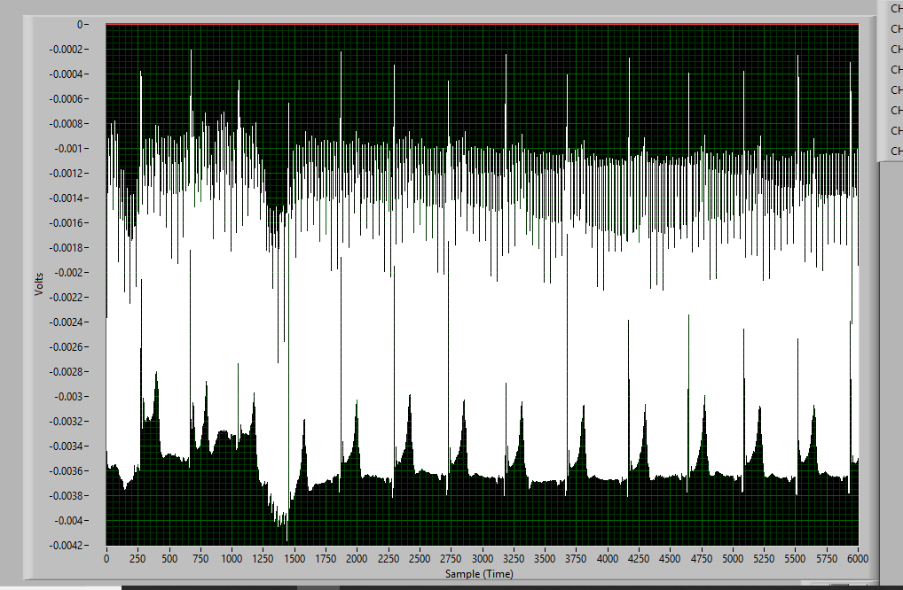
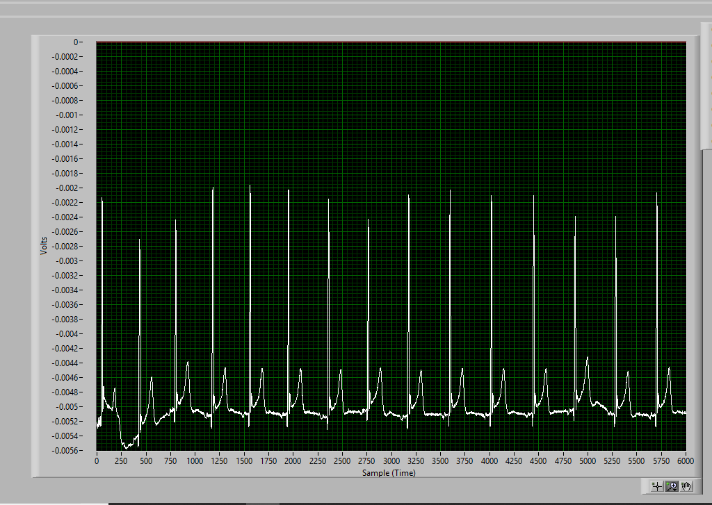
The problem I am having is I don't see an improvement in the common mode rejection with the RLD being disabled vs enabled, the FFT looks the same in both cases. I am mostly interested in rejecting 60hz noise.
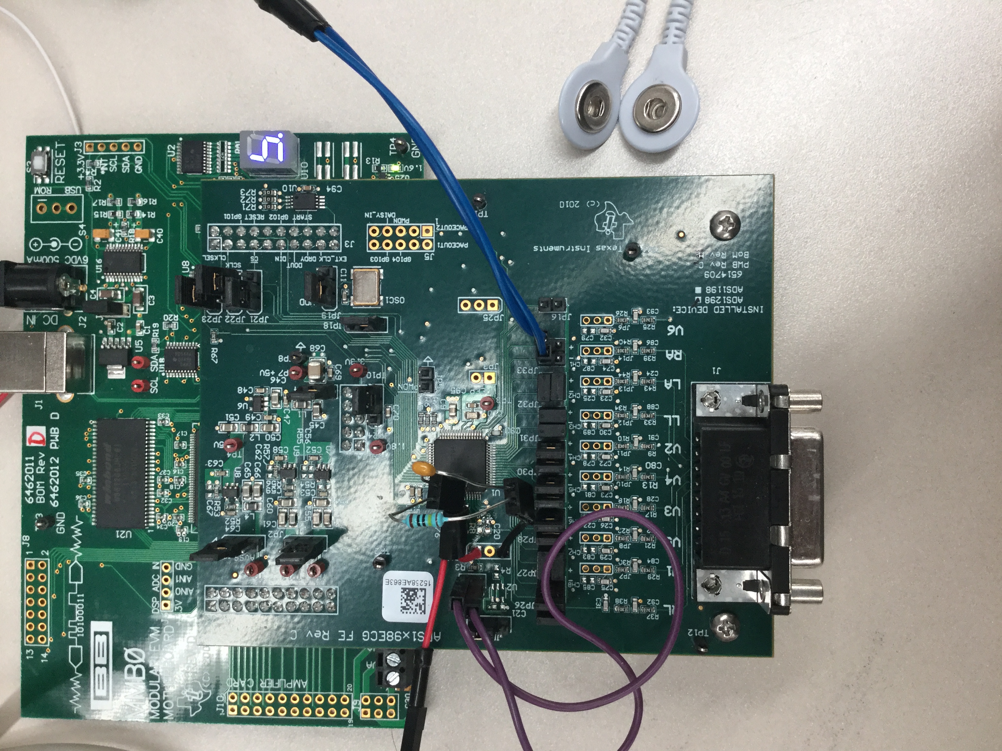
One of the TI forums suggested swapping the default 392Kohm||0.01uF (BW 40 hz) resistor and capacitor RLD loop (between RLDOUT AND RLDINV) on the board with something that has a higher bandwidth. I removed R8 and C20 and soldered female headers to RLDOUT and RLDINV so that I could place a different combination of resistor and capacitors, you can see it in the picture of the board I attached. I tried using 2.2 Mohm || 1nF (BW of 72 hz) and 1 Mohm || 1nf (BW of159 hz) , but with no success since the FFT looked the same with the RLD enabled or disabled.
The settings I am using are attached below. Thanks in advance for any help! :)
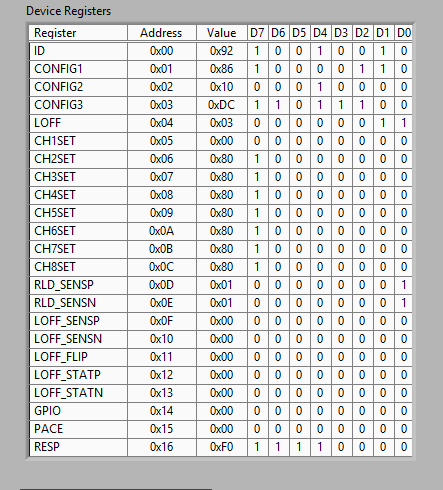
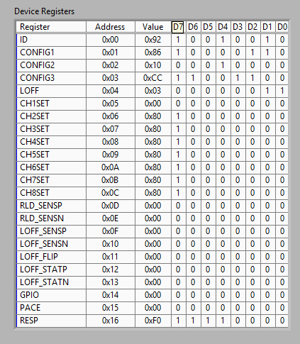
RLD Enabled Settings:
Register Settings:
ADS1298 PIN CONFIGURATIONS:
JP20-AVSS---CONNECTED TO GROUND
JP2--AVDD- 3V
JP1-CLOSED (RLD input to mux and RLD output connected)
JP17-RLDOUT pin connected to body
CH1- +/- ECG leads connected to body
Board Picture:
RLD Disabled and 1.5V common mode bias applied to body Settings:
Register Settings
ADS1298 PIN CONFIGURATIONS:
JP20-AVSS---CONNECTED TO GROUND
JP2--AVDD- 3V
JP1-OPEN (RLD input to mux and RLD output not connected)
JP17-RLDOUT pin connected to body ( Bias body with 1.5V)
CH1- +/- ECG leads connected to body
Board Picture: