This thread has been locked.

If you have a related question, please click the "Ask a related question" button in the top right corner. The newly created question will be automatically linked to this question.

ADS58B19: VCM Value

Part Number: ADS58B19

Tool/software:

hi sir 

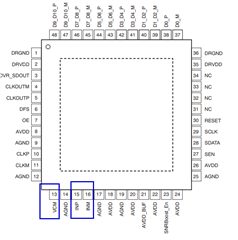
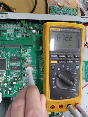
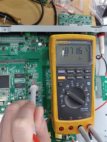
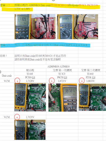
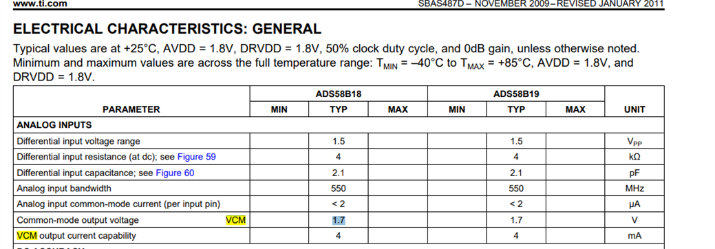
I Saw the data sheet, see the VCM is 1.7v

but i measure the chip in my pcb, which is 1.88?Why 

thanks

  • Hi,

    Please advise how you are measuring this? This is the pin 13 that you are measuring? This is not possible that the device generating a 1.88V output when the input voltage to the power supplies are all 1.8V based

    You can also measure the INP and INM pin to check the common mode voltage.

    -Kang

  • HI -Kang

    The ADS58B19IRGZT link with FPGA, I do some test, If I erase all the fpga firmware, the VCM change to 2.18v. WHY?

    may I know the VCM is fix or adjustable?

    if adjustable?  how to set up it?

    thanks

  • Hi Kang,

    May I have your help to check this issue?

    Customer is waiting for our feedback. Thanks.

  • Alex,

    VCM is fixed. Please measure the INP and INM as I had mentioned.

    I do not have visibility to your FPGA firmware, but most likely your power supplies on the board have issues and need further debug. 

  • hi 

    INP,INM Values as below

  • HI SIR

    Attach the test report & schmatic

    Test B version of the PCB.pdfLS FPGA B.pdf

  • HI,

    Thanks for the test report.  Please measure the 1p8_VD power supply.  Is it at correct level. 

    By removing the capacitors, you have disconnected the CLOCK input to the ADC (and VCM dropped to ~0.4V).  When the capacitors were connected (and VCM was 1.88V), was a clock being provided to the IC?

    regards,

    Ali  

  • Hello,

    The VCM may change depending on the clock rate input to the ADC. Please help check by inputting 250MHz clock into the ADC. You should be able to measure 1.7V VCM.

    At 25MHz clock rate, we measured 1.8V.

  • Hi Kang and Ali,

    We applied one EVM to customer for testing VCM. But still measure different VCM with different ADS58B19 date code.

    You can see below test result, customer did two experiment , yellow part showing experiment 1 result, customer use our EVM and change ADS58B19 device with two date code. You can see VCM have 1.71V and 1.88V. All condition is same, just only two different date code ADS58B19  and measure different VCM.  Date code 1 is 04J PCH9 G4 and Date code 2 is 7CJ P6CH G4. Do you have any suggestion?

    For experiment 2, customer use their design board to test three different date code and the device are purchased from Arrow.

    You can see blue part, Only 04J PCH9 G4 date code VCM is meet spec, for other two date code, the VCM value is wrong.

    Customer also test 250MHz / 200MHz / 100MHz, the VCM value is still 1.88V with 7CJ P6CH G4 and 84L P21K G4 date code.

    What's root cause for this case? Please check.

  • Hi,

    Please allow us some time to investigate this issue.  Note that the datasheet only specifies the VCM=1.7V as typical value.  Some variation is expected.

    How are you using the VCM in your design?  I cannot tell from schematic.  What variation in VCM can you tolerate?

    regards,

    Ali

  • Hi Ali,

    Noticed. If TYP is 1.7V, what's MAX value? I can't it from datasheet.

    I need to check your question and will update to you soon.

  • Hi Ali,

    Please see customer update as below.

    1. How are you using the VCM in your design? 

    The front-end design uses 1.7V. You can check schematic

    1. What variation in VCM can you tolerate?

    It's not a matter of tolerance or intolerance

    The chip exceeds specifications by 10%. Do you think it is reliable?

  • Hello 

    The common mode output voltage VCM has only a typical value of 1.7V in the datasheet. We expect the VCM to work across the range of 1.6V to 1.95V.

    Please advise the customer's impact on their analog front end. We believe if the customer can design their front end system to handle from 1.6V to 1.95V, then the ADC VCM should hold sufficiently. 

    Please also advise if the customer is using the ADC's VCM to bias their front end circuits. We believe they are doing so. Thank you.

    -Kang