This thread has been locked.

If you have a related question, please click the "Ask a related question" button in the top right corner. The newly created question will be automatically linked to this question.

ADS1292R: AED frontend

Part Number: ADS1292R

Tool/software:

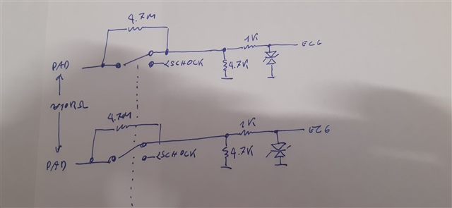
I am developing an automatic defibrillator and the ECG signal must be taken through 2 electrodes only, without the possibility of inserting an RLD connection to reduce the common mode signal. System requirements require that transthoracic impedance be measured both to determine discharge energy and to monitor chest compressions during resuscitation. I didn't find a reference design but only several ideas and I sketched a first scheme as follows, for simplicity I only show one of the two inputs, the other is identical:

Can I have some comments on this implementation?

Using Rldout to reduce the common mode signal is a good idea or is better get 1/2 of V_Ana using a resistive divisor?

For our experience if (for other considerations) i put a 4K7 resistor in parallel with TVS will the ECG signal be significantly disturbed or can I do it without major consequences?

Thanks for your kind reply, Paolo.

  • Hello Paolo,

    Thank you for your post.

    This implementation with a 68-MΩ pull-up resistor to RLDOUT looks ok. You can probably reduce the input AC coupling capacitor (i.e. C172) to 0.1µF and increase the high-pass corner frequency.

    What would be the purpose of the 4.7kΩ in parallel with the TVS diodes? I don't believe this will work for this application as it would significantly reduce the input impedance of the analog front-end.

    Regards,

    Ryan

  • Hello 

    Could you contact me ; i have  alot of experience about AED. 

  • Thanks for the reply.

    About the impedence of the front end yes, Yes, I too have doubts about the input impedance, but a resistor in that position would be very handy. I thought that since the patient's impedance is between 30 and 150 ohms (at least if we are referring to a defibrillatable patient) it should not alter the signal too much.
    The resistor would be needed because I want to use the safety relay that separates the patient from the high-voltage circuit used during defibrillation to disconnect the protection circuit made with two 1 K resistors and the dischargers from the patient, which would absorb a significant portion of the energy, thus allowing most of the energy to be directed towards the patient.
    However, since the regulations require that the discharge be recorded anyway, I would put two high-value resistors to receive the pulse on the ECG section anyway and, at this point, inserting two more resistors to form a divider would allow me not to saturate the ADC and record not only the fact that the discharge has taken place but also the voltage trend.
    In fact, the input impedance would become about 10KOhm, more than an order of magnitude higher than that of the patient, which is why I hope it will not disturb the ECG reading too much.

    In any case, if the two resistors create too many problems during cardiac monitoring, I can always decide not to mount them but, as I have already said, I would like to be able to precisely monitor the discharge progress.
    Obviously any ideas on the matter are welcome.
    Paolo Rozzi
    Sintéleia srl