Tool/software:
Hi guys.
I would like to use the ADS114S08B to apply four indipendent 2-wire PT1000 RTD.
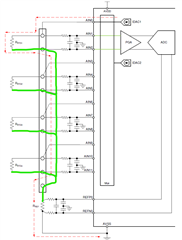
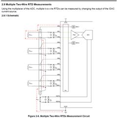
I would like to use the circuit that show in Figure 2-9 on SBAA275A (the image is visible below).
I need to measure the temperature from -40°C to +220°C with PT1000 sensors. This means to have RTDmin=842.7Ohm (-40°C) and RTDmax=1831.9Ohm (+220°C).
I set the IDAC to 250uA because the current suggest to flow into the PT1000 that I choose is from 100uA to 300uA.
With this current value, the maximum voltage across one PT1000 is VRTD_MAX=IDAC*RTD_MAX=250uA*1831.9Ohm=458mV.
Now I don't undestand which is the correct value of the PGA gain that i set. How can I choose this? 1 it's OK? 2? 4?
After that, the VREFMIN is VREFMIN=PGA gain*VRTD_MAX and we took the 10% margin, so VREF=1.1*VREFMIN.
With VREF value I can calculate the RREF with: RREF=VREF/IDAC. Is it correct?
The second step is to calculate the correct value of the R-C filter to the ADC inputs. Can you explait to me the method to calculate the correct values of the R-C filters?
Thanks.
Gabriele.