A related question is a question created from another question. When the related question is created, it will be automatically linked to the original question.
If you have a related question, please click the "Ask a related question" button in the top right corner. The newly created question will be automatically linked to this question.
Please see below my review list and bold marked line items which should be checked again
Checked with Quickstart Calculator
Rcs in series with inductor and before inductor
Check filter for Rcs Current sense Resistor Rcs does not have the required filter
Check filter for Risns Current sense Resistor Risns does not have the filter - recommend to add place holder
Connect IMONOUT to VCC if ISNS not used
Snubber on SW1 and SW2 Place Footprint for a snubber at SW1 and SW2 (they can then be populated in case needed (e.g. due to EMI) without layout change) Note: Snubber connect Resistor to GND for better Thermal performance
BIAS connected If BIAS is not used connect to GND or VIN of VOUT (do not keep open)
Add Series Resistor into MOSFET Gate signals lines (they can then be replaced in case needed (e.g. due to EMI) without layout change, additional option: add a diode in parallel for slow on and fast off.
Voltage rating of MOSFET (Have a margin of 30% is recommended)
Miller Plateau of MOSFETs used MOSFETs need to be logic level MOSFETs - can be seen by Miller Plateau in the range of 2.5V-3.5V
UVLO setting relative to lowest input voltage UVLO is set to xV but operating range starts at xV - relative large distance
Cap at VCC 22uF : (Datasheet min: 6uF with DC Bias) please check the cap on Vcc to have the required capacitance considering DC BIAS - we use a 22uF on the EVM
VCC2 is for control and driver supply VCC1 can used for external logic - if not used can be disabled
Feedback divider identical for FB and FBIN (check if FBIN is required)
FB_IN required: for pass through mode - only with external FB divider. With internal FB (FB connected to VCC2) put this to AGND
LM51772: Connect FB to VCC2 if voltage should be set via I2C -> please check if VOUT should be set via I2C
nRST if not used needs to be connected to VIN
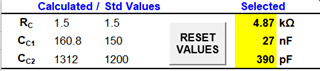
65W design:
Phase margin is low for 6V input.
Better with
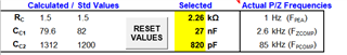
20W design:
Phase margin is low for 6V input.
Better with
Notes:
- it is not clear what should assembled and what not - e.g. check components on FB
- Device is LM51772RHAR (not PLM51772RHAR) - could not track signals as search did not work in pdf of schematic
- adding a resistor divider on EN_UVLO between VIN and GND would allow to disable the LM51772 when input is low. To disable via Controller pull pin low via a Diode. Note: might need to be protected with a Zener for high input voltages.
- a newer version of the quickstart calculator has been published
we will make adjustments In addition, EVM is currently used to use i2c address 0xA to adjust OCP, but the actual measurement seems to be very different. Any suggestions?