This thread has been locked.
If you have a related question, please click the "Ask a related question" button in the top right corner. The newly created question will be automatically linked to this question.
Tool/software:
Dear TI,
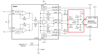
Can you advise please? We are using the INA851RGT fully differential instrumentation amplifier (INAMP) to drive the ADS1278MPAPTEP Differential ADC.
We are adding lowpass filtering to the INAMP to reduce the maximum output frequency into the ADC, in order to satisfy the Nyquist criteron. Our desired ADC Sampling Rate is 9 kSps, so our lowpass filter break frequency is 4.5 kHz.
We are adding two sets of lowpass filters (LPF) on the INAMP for our prototype board with the intention of removing one to see the effect after we receive hardware.
For the first LPF in the feedback loop of the INAMP, using the internal INAMP Rf = 5 kOhm, we have calculated a Cf = 7.1 nF. Please confirm I am understanding correctly how to calculate filter values in the feedback loop of this INAMP?
For the second LPF at the output of the INAMP, we have used the TI Analog Engineer's Calculator software, Ver. 1.71 (Drive Wideband Delta-Sigma ADC page) to choose a Modulation frequency = 6.75MHz, Cfilt = 2nF, which yields an Rfilt/2 = 569 ohms.
I noticed on this thread you are recommending Rfilt/2 = 50 ohms, and Cfilt = 2.2nF. I want to make sure I am considering all the design constraints of the INAMP and the ADC. Did I calculate this Cfllt value incorrectly?
Thank you.
Hello Daniel,
Yes, your calculations are correct for the internal LP filter implementation. The cutoff frequency will be f-LP=1/2*Pi*5k*Cf. Setting f-LP=4.5kHz results in Cf=7.1nF.
Since you want to run the ADS1278 data rate at 9ksps, you will need to lower the clock frequency, which will also lower the modulator frequency. Using high-resolution mode, the output data rate will be f-DATA=f-CLK/512. Setting f-DATA=9k and solving for f-CLK=4.608MHz. The modulator frequency will then be f-MOD=f-CLK/4=1.152MHz.
The Analog Engineers Calculator tool assumes you are using a standard fully differential amplifier that has the open loop output impedance specified. In the case of the INA851, it has the feedback resistors integrated, and these specs are not available. For stability purposes, I recommend using the filter values specified in Figure 9-9 of the INA851 datasheet. The ADS127L11 is similar to the ADS1278 (single channel, latest generation wideband delta-sigma).
You may also want to consider using the ADS127L18; this is the latest generation version of the ADS1278, and includes many more filter options and has improved specifications.
Regards,
Keith Nicholas
Precision ADC Applications
Hi Keith,
Thank you very much for your answer. I have two follow-on questions:
1. In the ADS1278-ep datasheet (Page 37/44) the recommended holdup capacitor between the analog Input pins (AIN_P, AIN_N) is listed as 1 - 10 nF.
If this capacitor is reduced to 510 pF (Per the INA5851 datasheet, Figure 9-9), will that cause voltage droop at the ADC when that channel is sampled?
2. Do you know when the ADS127L18 will be available for production? What is its Lead finish/Ball material please?
Thank you,
-Daniel
Hello Daniel,
1. The input capacitor value is related to the maximum modulator frequency. Since you will be running at a much lower frequency than the maximum, the 560pF will provide similar performance as a 2.2nF cap at maximum speed. When driving delta-sigma inputs with a larger input capacitor, the input of the ADC can be approximated as an input impedance, which will create a voltage divider with the input resistors. This creates a systemic gain error, but can be calibrated as part of the system gain calibration.
2. ADS127L18 will be releasing very soon; sorry I cannot be more specific. We have pre-production samples available today as well as a full evaluation board if interested. Regarding the Lead finish, I am fairly certain that it is NIPDAU, but I will need to confirm.
Regards,
Keith
Hi Daniel,
Confirmed NiPdAu lead finish for the ADS127L18 package. Please note that the released part will be standard commercial grade, not -EP or other high reliability variant. If you need one of these specifications, then the ADS1278 is the preferred device.
The ADS127L18 should release in the next 2-3 months.
Regards,
Keith
Hi Keith,
Do these filtering values circled in RED apply to any Modulator Frequency selected by the ADS1278? Even a higher Modulator Frequency of 2.816 MHz?
It seems so, but I wanted to make sure they were purely a function of the INA851.
Thank you,
-Daniel
Hi Daniel,
Yes, the input filter values will work well over a range of input modulator frequencies. You could possibly optimize these values for different frequencies, but in general, you will not improve performance. The recommended values have been confirmed to work well specifically with the INA851, and should also work well for the ADS1278 inputs at lower modulator frequencies similar to your case.
Regards,
Keith