This thread has been locked.

If you have a related question, please click the "Ask a related question" button in the top right corner. The newly created question will be automatically linked to this question.

ADS1299: Measure using BIAS

Part Number: ADS1299

Tool/software:

Hi TI engineers,

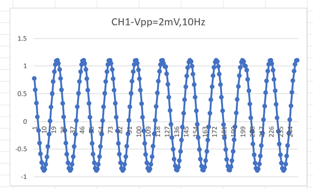
We have problem when using BIAS to measure ADC value,

We're measuring by channel 1.

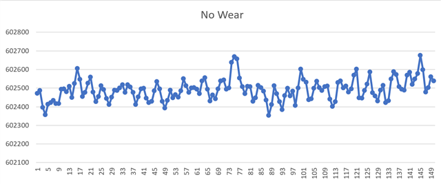
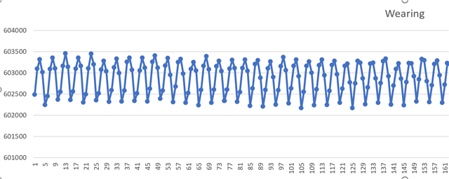
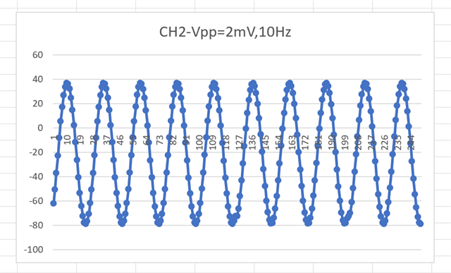
The issues is after I read data, seem it is verry small changes for each sample.

( This is some samples I combine from 3 bytes channel 1 to int:
 729037
 728863
 729045
 729435
 729399
 729124
 728936
 729191
 729582
 729466
 729112
)

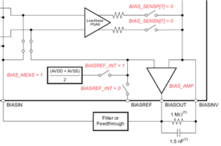
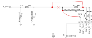
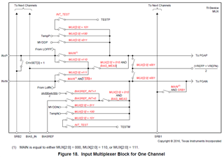
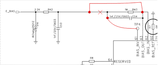
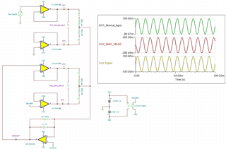
- This is our hardware design

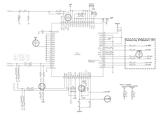
- And here are registers config:

CONFIG1 = 0xD6

CONFIG2 = 0xC0

CONFIG3 = 0xF6

LOFF = 0xE0

CH1SET = 0x52

MISC1 = 0x00

CONFIG4 = 0x02

BIAS_SENSP = 0x01

BIAS_SENSN = 0x01

LOFF_SENSP = 0x01

LOFF_SENSN = 0x01

Please help us that is our hardware  design can work in BIAS measurement, and is any problem with the register config

Best regards,

  • Hello Toan,

    Thank you for your post.

    The BIAS measurement will compare the voltage connected to the BIASIN pin to the selected BIASREF voltage as shown in Figure 38 in the data sheet (see below). In your configuration, you are using an external BIASREF voltage, which is connected to GND. I assume that you are using ±2.5V analog supplies and GND is your mid-supply reference?

    However, the BIAS amplifier circuit in your schematic is missing the feedback connection between BIASOUT and BIASINV (BIAS amplifier inverting input). The amplifier is operating in an open-loop configuration, so the output voltage at BIASOUT may be floating to approximately 30 mV. 30mV x 12V/V would result in the output codes you are observing.

    Please correct the BIAS circuit according to the markups below:

    Regards,

    Ryan

  • Hi Ryan,

    Thanks for your response, it's so clearify for me.

    I am chaging the hardware as you suggest then measure again.

    I will take result and need your support later.

    Best regards,

    Toan

  • Hi Ryan,

    After we changing hardware as you suggest, this is the result.

    (We're doing EEG applications, the resut includes two cases: when I no-wear device to the head, and when wearing device to the head)

    - When no-wear

    - When wearing

    You can see, the results changed when I start wearing device to the head. But I don't know the signal is normally. I see that the waveform is chaging, but the Voltage amptitude seem does not change to much.

    Please help us check this result.

    Best reagards,

    Toan

  • Hello Toan,

    The sinusoidal waveform you are observing in the second image is simply 50 Hz power line interference. This type of noise is common in bio-potential applications. The common-mode rejection of the system (ADS1299 + Bias electrode) can help to reduce the peak-to-peak amplitude of the 50-Hz noise, but any remaining noise is usually removed using some type of digital filtering (i.e. notch filter). 

    The actual EEG waveforms exist in different frequency ranges. We are not the experts when it comes to identifying proper EEG waveforms.

    Can you share the complete ADS1299 register configuration used for these measurements?

    Regards,

    Ryan

  • Hello Ryan,

    This is our register configuration:

    CONFIG1 = 0xD6

    CONFIG2 = 0xC0

    CONFIG3 = 0xF6

    LOFF = 0xE0

    CH1SET = 0x52

    MISC1 = 0x00

    CONFIG4 = 0x02

    BIAS_SENSP = 0x01

    BIAS_SENSN = 0x01

    LOFF_SENSP = 0x01

    LOFF_SENSN = 0x01

    Regards,

    Toan

  • Hi Toan,

    Thanks for sharing. As mentioned in my previous post, it's likely that your electrodes and lead wires are picking up power line interference. This is being sensed by the BIAS derivation circuit (BIAS_SENSP/N = 0x01) and driven to the BIAS amplifier output. You are measuring noise through CH1; however, in the real application, this signal would be driven back to the body and help to suppress the common-mode noise at the source.

    The setup and register settings seem correct. What is your next step in the prototype evaluation?

    Regards,

    Ryan

  • Hi Ryan,

    Thanks for your review!

    The noise measured when I wearing device to the body. It's same product on the production.

    We're setting up machine to genenate the waveform, and then using ADS1299 measure it again. We will need your support later.

    Regards,

    Toan

  • Thank you, Toan. Looking forward to your results.

    Regards,

    Ryan

  • Hi Ryand,

    Thank you for your patience.

    When I use WhaleTeq SEEG100  to generate sin waveform. The ADS1299 doesn't measure correct value in BIAS measurement. ( Note: When I configure ADS1299 as NON-BIAS measurement, I can see it capture waveform quite correct).

    I am connecting VINP to sin waveform. VINN and BIAS electrode to GND. (BIAS electrode is E_BIAS in my schematic)

    Seem have some incorrect in my measure method when my software config as BIAS measurement.

    Regards,

    Toan

  • Hello Toan,

    When the channel MUX setting is configured for bias measurement, the input switches to INP and INN are open. Please refer to Figure 18:

    Regards,

    Ryan

  • Hi Ryan,

    Do I ignore INP and INN, and just suppy sine waveform to BIAS electrode when software config as BIAS measurement?

    Regards,

    Toan

  • Hi Toan,

    I do not understand the reason for this test. Can you explain what is the goal of this measurement?

    Can you confirm that all tests are now conducted with the suggested modification completed?

    The BIAS measurement feature is primarily used as a diagnostic test to check the output of the BIAS amplifier. I would suggest the following to test both IN1P/N and BIASOUT simultaneously:

    1. Apply the input sine wave to IN1P. IN1N can be connected to GND. Confirm GND is shared between WhaleTeq and PCB GND.
    2. BIASOUT is the output of the internal BIAS amplifier. Is there an option on the WhaleTeq to connect the BIAS electrode? Otherwise, leave BIAS electrode floating. BIASOUT is routed to BIASIN pin on your schematic, so you can still measure it.
    3. Configure Channel 2 for BIAS measurement. CH2SET = 0x02.
    4. Set BIAS_SENSP = 0x01, BIAS_SENSN = 0x00.
    5. Read ADC output from both Channel 1 and Channel 2.

    Does this make sense?

    Regards,

    Ryan

  • Hi Ryan,

    I'm testing on hardware that modified as you suggest.

    The purpose of my test in BIAS measuremet is, I wan't see the waveform captured by ADS1299. Is it capture correct? And is it capture better than using Non-Bias measuremet.

    1. Apply the input sine wave to IN1P. IN1N can be connected to GND. Confirm GND is shared between WhaleTeq and PCB GND.
    => I tested it. (I'm thinking it is non-bias measuremet). The waveform captured by ADS1299 quite correct.

    I don't understand in your suggest config CH2 for BIAS measuremet: I don't see the sine waveform suppy in this test. Which input signal does CH2 measure to compare the output result?

    Please help me clarify!

    Thanks,
    Toan

  • Hello Toan,

    The test I suggested allows you to measure the sine wave through CH1 (normal input path) and CH2 (internal BIAS measurement) at the same time. CH2 register settings are configured to measure BIASIN - BIASREF (PGA2P = BIASIN, PGA2N = BIASREF).

    Please find the TINA simulation below. I hope this helps to explain the register configuration I suggested in my previous post. You can see how Normal Input and BIAS_MEAS channels are configured:

    ADS1299_BIAS_MEAS.TSC

    Regards,

    Ryan

  • Hi Ryan,

    Thank you for taking the time to help create the diagram.

    I will measure both channel1 and channel2 as your suggest and check results.

    Thanks,

    Toan

  • Hi Ryan,

    After follow your setup measure both CH1 and CH2, I can see the waveform of CH1 same with CH2

    Note (I change CH2SET = 0x02 to 0x62 for gain)

    This is the results:

    CH1

    CH2:

    This is the registers:

    Reg 0x00 0x3c
    Reg 0x01 0xd6
    Reg 0x02 0xc0
    Reg 0x03 0xf6
    Reg 0x04 0xe0
    Reg 0x05 0x60
    Reg 0x06 0x62
    Reg 0x07 0x81
    Reg 0x08 0x81
    Reg 0x09 0x61
    Reg 0x0a 0x61
    Reg 0x0b 0x61
    Reg 0x0c 0x61
    Reg 0x0d 0x01
    Reg 0x0e 0x00
    Reg 0x0f 0x01
    Reg 0x10 0x01
    Reg 0x11 0x00
    Reg 0x12 0x02
    Reg 0x13 0x00
    Reg 0x14 0x0f
    Reg 0x15 0x00
    Reg 0x16 0x00
    Reg 0x17 0x02

    Is my measure result correct with the config registers.

    Regards,

    Toan

  • Hi Toan - yes, the results look as expected. Feel free to begin a new thread if you need future assistance.

    Regards,

    Ryan

  • Hi Ryan,

    Thank you so much for your long time support. I really appreciate it!

    Regards,

    Toan