This thread has been locked.

If you have a related question, please click the "Ask a related question" button in the top right corner. The newly created question will be automatically linked to this question.

ADS131M08: response of

Part Number: ADS131M08

Tool/software:

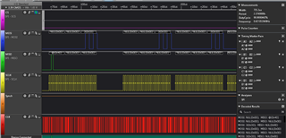
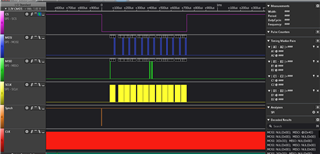
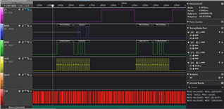
Hello, On page 42 of data sheet , if we send 0x22 (standby) we should receive (0x22) but in reality I am getting 0x94 as you can see from the following screen shot : we first send 0x22 , then null to read the response

  • Hello Saad,

    It appears you are using 16b SPI frames.  In order to use a 16b SPI frame, you must set the word size to 16b in the MODE register and disable all ADC channels in the CLOCK register.  Otherwise, after power-up, each frame should be 10 words in length, with each word equal to 24b.

    The proper SPI frame to send standby after power-up defaults would be as follows:

    1.  Start frame with nCS low.

    2.  Send the STANDBY command 0x002200h, followed by 9 more 24b words all at zero (Assumes SPI input CRC is disabled).  The total number number of SCLKs will be 240.

    3.  End frame with nCS high.

    4.  Send next frame, 240 SCLKs.  The response should be 0x002200h for the first word, followed by 9 more words.

    For most commands, there are ten words in a frame. On DIN, the host provides the command, the command CRC if input CRC is enabled or a word of zeros if input CRC is disabled, and eight additional words of zeros. Simultaneously on DOUT, the device outputs the response from the previous frame command, eight words of ADC data representing the eight ADC channels, and a CRC word. Figure 8-18 illustrates a typical command frame structure.

     Regards,
    Keith Nicholas
    Precision ADC Applications

  • Hello Keith, you mean that the default bit number at power up is 24bits so we have to send 24bits long words . That sounds logical.

    But why do we need to send 10 x 24bits?!

    if this is mandatory, shall we always send 10 words to write any command ?

    can we start directly to set the mode register ( or any other)  without going in standby? and if we set it to 16bits , shall we send 10x16bits frames to write commands always?

    does this setup effect the data reading?

    Sorry for the multiple question . The data sheet is not clear

  • Hello Saad,

    After further review, I confirmed you can just send 24b command for STANDBY, but a typical SPI frame will consist of 10 words, with each word size at 24b default after power-up.

    We recommend sending the STANDBY command to stop ADC conversions before writing to other configuration registers.  Once you are in STANDBY, you can then configure the device for 16b words.

    When in STANDBY, you can update the registers and either use the full 10 word frame, or, use short frames since the ADCs are disabled.

    After you start conversions by sending the WAKEUP command, you should always use 10 words, or 160 SCLKs with 16b word size selected.

    Regards,
    Keith

  • Hello Keith,

    I did try to send one 24 bit and then try to get the response . It did not work . Response is different

    I then tried to continue sending 0x33 12 times to see what I get but there is no 0x33. By doing this I get some response at the 7th interrogation but it is not correct.

    Followings are two screen shots , of same acquisition :

  • Hello Saad,

    You need to send 0x003300h for the Wakeup command and default word size of 24b.  In addition, the total SPI frame size should not be more than 10 words, except for the RREG and WREG cases where multiple register read/writes exceed the 10 word limit.

    I would also suggest you look closely at the SCLK signal directly on the ADS131M08 pin to verify it is a clean signal.  If there is a lot of ringing on the signal, the ADS131M08 may interpret this as multiple clocks, in which case communications would be corrupted.

    Regards,
    Keith