Tool/software:
I'm trying to use an ADS1115 to measure the voltage of a floating electrochemical (ORP) probe that produces +/-2V with a rather large output impedance. My nominal test case using tap water should come in right around 200mV. Right off the bat, I realize now that this is not likely to go well without using an input buffer, since I get acceptable measurements using a DMM with input impedance of 16Mohm, yet load the sensor down noticeably when using a DMM with Z=10Mohm (on the mV scales, each).
So of course, when using the bare ADS1115 in any mode, it's going to load the sensor unacceptably. But what I'm stuck on is that the impact seems to be MUCH worse than it SHOULD be. Plugging the sensor into the lower-z multimeter loads it down from 200mV to settle at maybe 120mV. Plugging it into the ADC clamps it to like 22mV almost instantly. I was so confused by this I even bought a new, definitely-not-counterfeit part suspecting that my original breakout board was shady, but the behavior is identical.
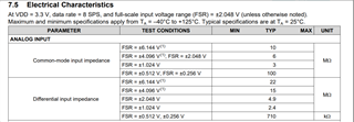
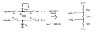
Using the sensor in 6.144V full scale and 8sps modes, it should have Z = Zdiff||Zcm = 10M||22M||22M = about 5.23Mohm, right?
Measuring with a multimeter in ohms mode stuck right across the inputs produces mixed results depending on the meter. One consistently reads ~3.5 to 4Mohm while the ADC shows its test voltage is around 3.6V. Another autoranges too quickly to get a result. Yet another shows about 1Mohm, while the ADC reads 200mV. The true resistance as measured by the DMM depends on its range and excitation voltage, and the particular part of the sampling phase the ADC is in.
It very much looks like there's some static (differential) input current on top of the resistance-approximating input impedance expected.
To try to get a better understanding, I drove the differential input with a floating bench supply at 0.51V per the following diagram:
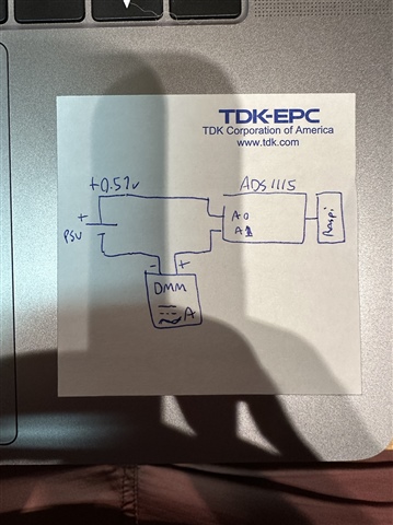
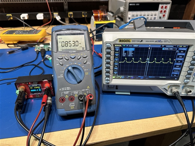
Note that the DMM is set to RMS AC+DC current mode, since the current waveform pulses. I had also tried using a current shunt amplifier (LowPowerLabs Current Ranger) and my oscilloscope, which produced the very pulse-y waveform at the bottom of this post. I noticed at that point that my DMM measurement disagreed with the RMS measurement on the scope, at which point I switched to the proper DC+AC mode on the meter and then became confident in that measurement.
Measuring this way, I saw that the bench PSU was sourcing 6uA DC+AC into the ADC, which at 0.51V works out to 85kOhm (!!!)
To check the operating mode, I manually changed the sample rate up from 8sps, and manually changed the full scale range down (gain up) both of which resulted in yet higher current drawn from the PSU. I confirmed that of all combinations, 6.144V FSR and 8sps resulted in the lowest current measurement I could achieve.
One final thing I did notice: when I leave the ADC floating entirely, it measures between -20 and -200mV depending on how much wire is attached (so that's mainly noise-related I guess?) When shorted, it measures identically 0. When connected to PSU+ only, it measures ~700mV (whether the PSU is on or off). When connected to PSU- only, it measures ~-700mV (again, whether on or off. However, those measurements seem roughly consistent with "a random length of wire" in place of "PSU+/-" so I'm attributing that to behavior in the presence of ambient capacitance.
So anyway, what am I doing wrong or misunderstanding that this input impedance seems so much lower than expected?
Here's that waveform I mentioned. Ignore the DMM and RMS scope measurements, these were taken at a different input voltage from the 0.51V above.