This thread has been locked.

If you have a related question, please click the "Ask a related question" button in the top right corner. The newly created question will be automatically linked to this question.

ADS1296R: CH4 as PACE input noisy

Part Number: ADS1296R

Tool/software:

We are using ADS1296R in 5 electrode ECG mode.

CH1 : Used for Respiration

CH2 used for Lead I , CH3 used for Lead II , CH4 used for Lead III , CH5 used for V1

When we use CH4 as Pace input the pace signal is too noisy. We use hardware slope detection circuit. But if we switch to CH2 or CH3 as Pace input we dont see any noise.

We doubt our hardware so, we swapped Lead II to CH4 and Lead III to CH3 in PCB , but still CH4 as Pace input still remain noisy.

We also tried with "Input Short" in CH4 , still CH4 as Pace input remain noisy.

But Input Short CH2 , CH3 as Pace input is clean 

Need immediate help... 

  • Hi Raghavendra,

    Thank you for your post.

    When CH4 is selected as the PACE channel, the output is always using PACE_OUT1 and the associated PACE amplifier. Can you compare the pace output with Lead III connected to CH3 and PACE_OUT2 vs. CH4 and PACE_OUT1? Please share the device register settings for both tests.

    Regards,

    Ryan

  • Thanks Ryan..

    Lead III (LA-LL) connected to CH4 , and CH4 as PACE input and PACE_OUT1 used as Pacer.
    REG-CHnSET:
    CH1 = 0x00  // Input (Respiration)
    CH2 = 0x00 // Input (Unused)
    CH3 = 0x07 // RLD drive to RA
    CH4 = 0x00 // Input (LA-LL)
    CH5 = 0x81 // Input short & Power down 
    CH6 = 0x81 // Input short & Power down
    REG-PACE = 0x0D // CH4 & CH5 are Pace inputs
    In this configuration the PACE output is noisy.
    Lead III (LA-LL) connected to CH3 , and CH3 as PACE input and PACE_OUT2 used as Pacer.
    REG-CHnSET:
    CH1 = 0x00  // Input (Respiration)
    CH2 = 0x00 // Input (Unused)
    CH3 = 0x00 // Input (LA-LL)
    CH4 = 0x07 // RLD drive to RA
    CH5 = 0x00 // Input (Unused)
    CH6 = 0x81 // Input short & Power down
    REG-PACE = 0x13 // CH3 & CH6 are Pace inputs
    In this configuration the PACE output is clean.

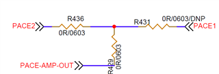
    Note : PACE1 and PACE2 are the outputs from ADS1296R . Resistors R436 & R431 are 1K ohm . PACE-AMP-OUT is fed to Slope detector for hardware pace detection.
  • Thanks, Raghavendra. 

    Are both R436 and R431 installed at the same time? I wonder if there's some contention issue between the two PACE amplifiers, even though the channel input to one of them is set to 0x81. Can you remove R436 in the first test case (PACEOUT1 = CH4) and test it? Please share the clean and noisy results so I can compare on the bench this week.

    Regards,

    Ryan

  • Hello Ryan.

    Yes, we had the same doubt , so we removed R436 and tested. The result is same CH4 as Pace input is noisy.

  • Hi Raghavendra, can you please share the results from each test for comparison? I assume you are checking this on a scope. I will be testing this later this afternoon.

    Regards,

    Ryan

  • Hello Raghavendra,

    I am not able to see any difference in the noise outputs between PACEOUT1 and PACEOUT2. 

    In one test, I tested CH3 and CH4 one at a time with a 100-Hz, 100-mVpp sine wave. While one was set to normal electrode, Gain = 6, the other channel was powered-down and set to input-short. Input sine wave was connected to INxP and GND to INxN (analog supplies are set to ±2.5V). Selecting each channel to connect to the corresponding PACEOUT pins (one at a time) yields the same output for both. 

    I also measured the RMS noise with the source output disabled (probes set to 300MHz BW):

    • CH4 to PACEOUT1, 2.77 mVrms (source off)
      CH3 to PACEOUT2, 2.97 mVrms (source off)

    Could you please share your results? Is the noise you are observing Gaussian or are there periodic spikes in the output?

    Again - please share the complete register settings as well to help us understand the exact configuration.

    Regards,

    Ryan

  • Hello Ryan,

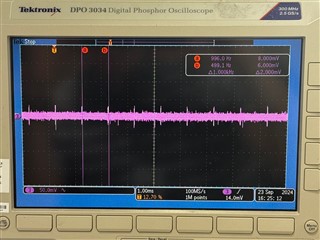
     What we noticed is the periodic spike. The repetition rate of this spike exactly matches to sampling rate what I configure to ADS1296R. I checked with 500Hz and 1KHz. The periodic spike repetition rate exactly changes as per configured sampling rate.

    Surprisingly this spike amplitude is high only with CH4 as PACE input , but very low with CH3 as PACE input.

    Please find the attached file for the Scope captures, for easy debug we tried between CH2 and CH4 instead of CH3 and CH4. The observation is CH2 and CH3 are clean , CH4 is noisy.

    CH3 as PACE Input:
    
    0 Write register opcode1  0x0041,
    
    1. Write register opcode2  0x0018,
    
    2. CONFIG1 0x0001  0x00A6,// 0x00A6 for 500 sps 0x00A5 for 1K sps
    
    3. CONFIG2  0x0010,
    
    4. CONFIG3  0x00EC,///0x00DC, 4V ref
    
    5. LOFF  0x004F,
    
    6. CH1SET (PGA gain = 6/4)  ((0x0000 & 0x8F) | PGA_GAIN_BITS ),
    
    7. CH2SET (PGA gain = 6/4)  ((0x0000 & 0x8F) | PGA_GAIN_BITS ),
    
    8. CH3SET (PGA gain = 6/4)  ((0x0000 & 0x8F) | PGA_GAIN_BITS ),
    
    9. CH4SET (PGA gain = 6/4)  ((0x0006 & 0x8F) | PGA_GAIN_BITS ),
    
    10. CH5SET (PGA gain = 6/4)  ((0x0081 & 0x8F) | PGA_GAIN_BITS ),
    
    11. CH6SET (PGA gain = 6/4)  ((0x0081 & 0x8F) | PGA_GAIN_BITS ),
    
    12. CH7SET (PGA gain = 6/4)  ((0x0000 & 0x8F) | PGA_GAIN_BITS ),
    
    13. CH8SET (PGA gain = 6/4)  ((0x0000 & 0x8F) | PGA_GAIN_BITS ),
    
    14. RLDSENSP (default)  0x0002,
    
    15. RLDSENSN (default)  0x0002,
    
    16. LOFF_SENSP  0x001A,
    
    17. LOFF_SENSN  0x0004,
    
    18. LOFF_FLIP (default) 0x0004,
    
    19. LOFF_STATP (Read only)  0x0000,
    
    20. LOFF_STATN (Read only)  0x0000,
    
    21. GPIO  0x000F,
    
    22. PACE (default)  0x0005,
    
    23. RESP (default)  0x00F2,
    
    24. CONFIG4  0x0022,
    
    25. WCT1  0x000C,
    
    26. WCT2  0x00D3,
    
    
    CH4 as PACE input :
    
    0 Write register opcode1
    		0x0041,
    1. Write register opcode2
    		0x0018,
    2. CONFIG1 0x0001
    		0x00A6,for 500 sps and 0x00A5 for 1K sps
    3. CONFIG2
    		0x0010,
    4. CONFIG3
    		0x00EC,///0x00DC, 4V ref
    5. LOFF
    		0x004F,
    6. CH1SET (PGA gain = 6/4)
    		((0x0000 & 0x8F) | PGA_GAIN_BITS ),  
    7. CH2SET (PGA gain = 6/4)
    		((0x0000 & 0x8F) | PGA_GAIN_BITS ),
    8. CH3SET (PGA gain = 6/4)
    		((0x0007 & 0x8F) | PGA_GAIN_BITS ),
    9. CH4SET (PGA gain = 6/4)
    		((0x0000 & 0x8F) | PGA_GAIN_BITS ),
    10. CH5SET (PGA gain = 6/4)
    		((0x0081 & 0x8F) | PGA_GAIN_BITS ),
    11. CH6SET (PGA gain = 6/4)
    		((0x0081 & 0x8F) | PGA_GAIN_BITS ), 
    12. CH7SET (PGA gain = 6/4)
    		((0x0000 & 0x8F) | PGA_GAIN_BITS ),
    13. CH8SET (PGA gain = 6/4)
    		((0x0000 & 0x8F) | PGA_GAIN_BITS ),
    14. RLDSENSP (default)
    		0x0008,
    15. RLDSENSN (default)
    		0x0008,
    16. LOFF_SENSP
    		0x001A,
    17. LOFF_SENSN,
    		0x0004,
    18. LOFF_FLIP (default)
    		0x0004,	
    19. LOFF_STATP (Read only)
    		0x0000,
    20. LOFF_STATN (Read only)
    		0x0000,
    21. GPIO
    		0x000F,
    22. PACE (default)
    		0x000D,	
    23. RESP (default)
    		0x00F2,
    24. CONFIG4
    		0x0022,
    25. WCT1
    		0x000C,
    26. WCT2
    		0x00D3,
    
    NOTE:-  PGA_GAIN_BITS = 4
    
    Reg config in ecg (probed).pdf

  • Hi Raghavendra,

    Thanks for sharing the code and register setup. I've summarized the important settings in each configuration below:

    LEAD I TEST

    • CH1, 2, 3, 7, 8 = NORMAL, G=4
    • CH5, 6 = PD, input-short
    • CH4 = RLD to IN4P
    • RLD_SENS = IN2P and IN2N
    • PACE1 (even) = CH2
    • PACE2 (odd) = CH5

    LEAD III TEST

    • CH1, 2, 4, 7, 8 = NORMAL, G=4
    • CH5, 6 = PD, input-short
    • CH3 = RLD to IN3N
    • RLD_SENS = IN4P and IN4N
    • PACE1 (even) = CH4
    • PACE2 (odd) = CH5

    I tested the above lead configurations while probing both PACE_OUT1 and PACE_OUT2. In all cases, including 500 SPS and 1k SPS, I'm not able to see the noise which you have shown in the PDF. There are some small spikes which occur at the data rate, but this only appears while SPI communication is active. Also, note that the y-axis scale on the scope is only 50 mV/div:

    I've attached the register configuration text files below used on the EVM GUI. The only difference I should point out from your PDF is that I disabled the RESP function. Otherwise, the RESP modulation signal swamps out the rest.

    LEAD_III_EVM.txt
    conf|config1	0x01	0xA6
    conf|config2	0x02	0x10
    conf|config3	0x03	0xEC
    conf|loff	0x04	0x4F
    conf|ch1set	0x05	0x40
    conf|ch2set	0x06	0x40
    conf|ch3set	0x07	0x47
    conf|ch4set	0x08	0x40
    conf|ch5set	0x09	0xC1
    conf|ch6set	0x0A	0xC1
    conf|ch7set	0x0B	0x40
    conf|ch8set	0x0C	0x40
    conf|rldsensp	0x0D	0x08
    conf|rldsensn	0x0E	0x08
    conf|loffsensp	0x0F	0x1A
    conf|loffsensn	0x10	0x04
    conf|loffflip	0x11	0x04
    conf|gpio	0x14	0x0F
    conf|pace	0x15	0x0D
    conf|resp	0x16	0x30
    conf|config4	0x17	0x22
    conf|wct1	0x18	0x0C
    conf|wct2	0x19	0xD3
    
    LEAD_I_EVM.txt
    conf|config1	0x01	0xA6
    conf|config2	0x02	0x10
    conf|config3	0x03	0xEC
    conf|loff	0x04	0x4F
    conf|ch1set	0x05	0x40
    conf|ch2set	0x06	0x40
    conf|ch3set	0x07	0x40
    conf|ch4set	0x08	0x46
    conf|ch5set	0x09	0xC1
    conf|ch6set	0x0A	0xC1
    conf|ch7set	0x0B	0x00
    conf|ch8set	0x0C	0x40
    conf|rldsensp	0x0D	0x02
    conf|rldsensn	0x0E	0x02
    conf|loffsensp	0x0F	0x1A
    conf|loffsensn	0x10	0x04
    conf|loffflip	0x11	0x04
    conf|gpio	0x14	0x0F
    conf|pace	0x15	0x05
    conf|resp	0x16	0x30
    conf|config4	0x17	0x22
    conf|wct1	0x18	0x0C
    conf|wct2	0x19	0xD3
    

    Regards,

    Ryan

  • Hello Ryan,

    Thanks. In our case also the SPI communication is active.

    Please note that we probes after the amplifier which amplifies PACE_OUT signal.

    The gain is 160 and comparator reference after the slope detector is 200mV.  Don't you think this creates false trigger of PACE due to periodic noise?

  • Hi Raghavendra,

    In case it is easier to share details offline, I will reach out to you via email.

    Understood that you are probing the PACE_OUT signals after the external amplifier on your PCB. I can see how the transients are getting close to the 200-mV detection threshold. 

    This issue still seems unique to CH4 = PACE_OUT1 in your system. Is it possible to move the same IN4P and IN4N electrodes to another even numbered channel (i.e. CH2, CH6, or CH8)? Leave everything else in the setup the same.

    Regards,

    Ryan