- Ask a related questionWhat is a related question?A related question is a question created from another question. When the related question is created, it will be automatically linked to the original question.
This thread has been locked.
If you have a related question, please click the "Ask a related question" button in the top right corner. The newly created question will be automatically linked to this question.
Tool/software:
 I purchased the AFE58JD48EVM and TSW14J50 modules for development. However, during the experiment, I found that channels 3, 4, 15, and 16 of the AFE58JD48EVM could not collect signals, while the remaining channels were normal. What is the reason for this? Secondly, there will be a DC offset of about 1 to 10 mV in each channel (I have enabled the HPF in the LNA part). Is this a normal phenomenon? What is the cause? Finally, out of my curiosity, since we have already implemented a data acquisition system based on AFE5812 before, I want to know whether the LNA of AFE58JD48 realizes HPF by connecting an operational amplifier at the LNA output to implement integral feedback for high-pass filtering? Is its HPF transfer function HPF1 in the AFE58JD48 data sheet? Thank you and look forward to your reply.
Hi,
We dont expect this behavior.
What do you mean by not getting signal ? Is it noise around 0V ? Can you probe near the input of device to check the signal ? This we can isolate the issue is with PCB or device.
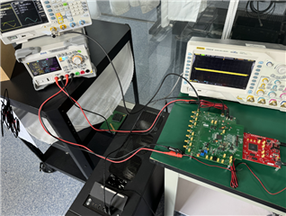
Hi ! I conducted the test again today. The channels 3, 4, 15, and 16 mentioned before still cannot work. That is, only a 0V signal is collected back (of course, there will be a few mV of noise). According to your suggestion, I used an oscilloscope to test at the reserved test point of the SMA port of the AFE58JD48EVM on channels 3, 4, 15, and 16. I found that the input analog signal can be detected. At present, the reasons of the SMA interface and input signal can be excluded. What should I do next?
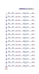
Can you probe near device . There in a 50 ohm termination near to device .You can probe that point .
It is very unlikely to that few channels in device is not working . What is SNR you are seeing in idle channel across these channel vs good channel ? You can check this at high gain/low gain.

Hi,I used an oscilloscope to test R25 (channel two, good channel) and R26 (channel three, faulty channel). I was able to detect the input analog signal at the resistors for both. Regarding the SNR of the idle channel, I tried low gain and high gain and did not find any significant difference between the faulty channel and the good channel. If it's convenient for you, you can give me your email address and I can send you the relevant experimental results. In addition, what I am more concerned about is how the TX_TRIG pin that I asked about earlier should be connected to the FPGA or other AFE chips in my actual development to work properly.
Till resistor it is coming . So next suspect is input coupling cap or device. If there is a probing point after the cap you can probe there.
One more experiment you can try . Power supply current is dependent on signal . So for good and bad channel with and without signal (full swing) you can check the power supply current .
You can mail to this address ultrasound_rx-support@list.ti.com .