This thread has been locked.

If you have a related question, please click the "Ask a related question" button in the top right corner. The newly created question will be automatically linked to this question.

ADS114S08: Issue with Random Values from ADS114S08 When RTD Sensor is Not Connected

Part Number: ADS114S08

Tool/software:

Hello Team

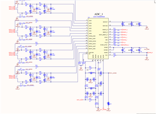
I am currently working with the ADS114S08 in a circuit designed to measure temperature using a 4-wire RTD configuration. Our system is set up to handle 4 channels of the ADC, and we are experiencing some issues when no RTD sensor is connected to the respective input channels.

When the RTD sensors are not connected, the input channels are floating, and we have observed unpredictable and fluctuating ADC readings between 8000h and 7FFFh. As described in the ADS114S08 datasheet, these values are likely the result of stray electromagnetic fields, thermal noise, or other environmental factors affecting the floating inputs.

Given this, we are considering the use of a pull-down resistor to mitigate the noise and stabilize the input channels when no sensor is connected. However, before proceeding, we would like to confirm the following:

Is it advisable to use a pull-down resistor in this configuration, and if so, what resistance value would be recommended?
Where in the circuit would be the most effective location to place this pull-down resistor?
Are there any other recommended best practices or design techniques to minimize the random ADC readings caused by noise when no RTD sensor is connected?


We would appreciate any guidance or recommendations you could provide on how to address this issue and improve the stability of our measurements.

Thank you in advance for your support. I look forward to your expert advice.

Best Regards

Prashant Gautam
  • Hi Prashant Gautam,

    When the RTDs are disconnected, why does it matter what the inputs read? Are you trying to detect wire breaks? If so, you can refer to this document for more information about how to detect wire breaks: https://www.ti.com/lit/pdf/sbaa483

    Also, you are going to get some significant errors due to the multiple 30k resistors in the input path. I would recommend reducing these values by a factor of 10x. The gain error associated with the reference resistor is >10% because of these resistors + 1Mohm pull-together resistor on the inputs

    -Bryan

  • yes i am trying to detect wire breaks to monitoring the 4-wire RTD, and I am utilizing your [ADS114S08] for this purpose. I have configured the relevant registers to monitor the reference voltage (Vref) for wire break detection as per the documentation. However, I am still not receiving the expected status indicating a wire break.

    Could you kindly assist by confirming if there are any additional configurations or settings required to properly detect wire breaks in this setup? Additionally, if there are any specific troubleshooting steps or suggestions to ensure the wire break detection is functioning correctly, I would greatly appreciate your guidance.

    Best Regards

    Prashant Gautam

     register configuration.docx

  • Hi Prashant Gautam,

    There is different behavior depending on which wire breaks: if the top or bottom lead of the 4-wire RTD breaks, then you should get an error in the FL_REF_Lx flags in the STATUS register. This assumes you have the VREF flags enabled (see the REF register)

    If either of the signal lines break, then you will need to enable the burnout current sources (BOCS) or IDACs to route current through these pins. This is described in section 3.3.1 and 3.3.2 in the application note I provided in my last post. You should also complete this in a separate diagnostic step so you do not interfere with the RTD measurement

    Alternatively, you could add pull-up / pull-down resistors (>=1Mohm) on the inputs, however this would have to be between the RTD and the 30k resistors to avoid drawing current through the 30k resistors. Either way, this will draw some current from the IDAC and result in a gain error.

    -Bryan