Part Number: ADS1115
Other Parts Discussed in Thread: ADS1220, ADS131M02
Tool/software:
Hello,
I am currently working with the ADS1115 ADC and STM32f4,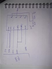 in my project to measure current changes across an AC load using a CT sensor. I have encountered fluctuations in ADC readings when using single-ended mode, but the readings are stable in differential mode. Below are the details of my configuration and issue:
Configuration:
I need to operate ADC in continous mode not in single shot mode so using conversion ready signal in ALERT/READY pin i am reading the value stored in conversion register. According to the information in data sheet i setted the High_threshold register msb with 1 (the value i wrote is 0x8000) and low threshold register MSB to 0 (the value i wrote to this register is 0x0000)
-
ADS1115 Settings:
- OS bit: 0 (conversion is not in progress)
- MUX[14:12]:
- For differential mode (the following i checked with):
001: AINP = AIN0, AINN = AIN3010: AINP = AIN1, AINN = AIN3011: AINP = AIN2, AINN = AIN3
- For single-ended mode:
100: AINP = AIN0, AINN = GND101: AINP = AIN1, AINN = GND110: AINP = AIN2, AINN = GND111: AINP = AIN3, AINN = GND
- For differential mode (the following i checked with):
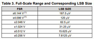
- FSR: checked with 2.048V and 4.096V and the formula used to convert the ADC value is voltage = ((adc_value * FSR * 1000) / 32768);
- Data Rate: 128SPS
- Comparator Mode: Zero
- Comparator Polarity: One
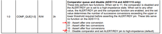
- Comp_que: Set to 00 (no comparator)
-
Hardware Setup:
- VDD: 5V connected to ADS1115
- Ground: Common ground across all components (ADS1115, STM32 microcontroller, and voltage divider)
- Input Voltage for Testing: 3.3V from the STM32 microcontroller, stepped down to 1.651V using a voltage divider circuit (2 resistors, each 1kΩ).
- Test Signals: Used a multimeter to verify input voltage at 1.651V.
Observations:
-
Fluctuations in Single-Ended Mode:
- When I apply 1.651V to the input (AIN0), I observe fluctuations in the ADC readings. The values are not constant and vary in a range like 1.601V, 1.624V, and 1.532V at different times. I am difficult to predict the variation.
-
Offset Readings:
- When I check the ADC value with 0V input (to measure offset), I observe fluctuating negative values like -0.101V, -0.92V, and -0.27V at different times. These values are inconsistent, making it difficult to calibrate the offset error.
-
Stable Readings in Differential Mode:
- When I switch to differential mode (AINP = AIN0, AINN = AIN3), the ADC shows stable and correct readings: 1.653V when applying the input voltage and 0V when measuring the offset by connecting 0V.
Questions:
- Why am I observing these fluctuations in single-ended mode?
- What could be causing the offset errors in single-ended mode, and how can I correct them?
- Is there a way to stabilize the ADC readings in single-ended mode, similar to the stable readings in differential mode?
- How can I add the offset values for proper calibration in my application?
Any help, suggestions, or guidance on how to resolve this issue would be greatly appreciated!
- When I switch to differential mode (AINP = AIN0, AINN = AIN3), the ADC shows stable and correct readings: 1.653V when applying the input voltage and 0V when measuring the offset by connecting 0V.