Tool/software:
Hello,
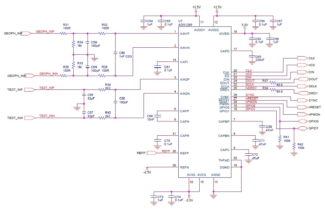
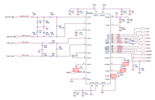
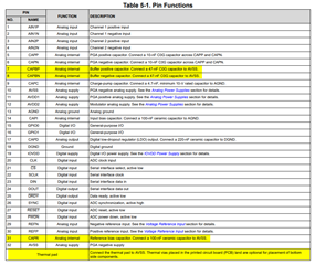
we have been trying to figure out why a board featuring three ADS1285 ADCs is absorbing a lot of current from the negative supply. Our circuit has bipolar power supplies for the analog section. ADS1285 AVDD1 and AVDD2 are connected to +2.5V, AVSS to -2.5V. IOVDD is set to 3.3V and the CAPD pin is not connected to IOVDD. Please, refer to the schematics below for more details.

The current consumption starts from normal values (about 10mA) when the baord is powered on. However, it gradually increases until the negative power circuit reaches its current limit. When the power circuit is no longer able to regulate the output voltage, voltage stabilizes at around -2V, rather than -2.5V. Using a thermal camera, we observed that the ADCs heat up significantly more than the sorrounding components. Unfortunately, I cannot share images from the camera right now, but I will do it as soon as possible. I would appreciate it if anyone could review the attached schematic and identify any potential errors that could explain this unexpected behavior.
EDIT: the negative supply ciruit is based on the negative LDO TPS72325 with 200 mA output current, but we were using an external power supply with 1 A output current when looking at the circuit through the thermal camera. The external supply was connected directly to -2.5V while the negative LDO's output was disconnected from the rest.
Regards, Gioacchino


