ADS7958: MUX staying in ch0 and not switching further

Part Number: ADS7958
Other Parts Discussed in Thread: ADS7959

Tool/software:

Hi Team, 

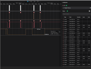
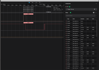
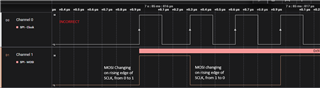
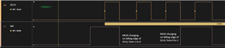
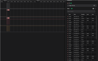
We are facing issues with the ADS7958 chip, we were previously working with ADS7959 for an older version of the board. Right now with the new revision we went with ADS7958 main reason being we only need 4 channels now. When we bought up the SARADC we observed that same data from ch0 is being copied to every channel upon further digging with logic analyzer we saw that the channel switching is not happening as you can see from the below screenshot attached. 

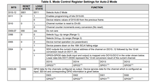
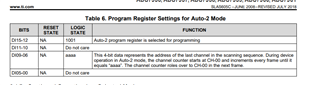
The configurations that I was running is on AUTO-2 mode which is set by (0x3c00)-->(0b0011110000000000), Also we configured AUTO-2 mode to only count till ch3 and reset back to 0 using (0x9180)-->(0b1001000011000000), In the screenshot below we ran with 0x91C0 which counts up to 4 we later changed it to 0x9180 still didn't work.

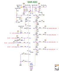
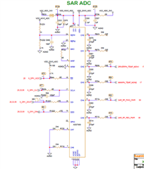
Attaching images of LA and schematic for reference

Thanks & Regards,

George

  • Hi George,

    I greatly appreciate you attaching the logic analyzer captures in the first post :)

    I think the issue is the second frame, programming the Auto-2 mode program register. Your input is 0x91C0, or 1001 0001 1100 0000. The last channel in the sequence is specified by bits 9-6. I've highlighted them here: 1001 0001 1100 0000. 

    0111 corresponds to channel 7. You then mention you changed it to 0x9180 (1001 0001 1000 0000), This doesn't solve the issue, as you're selecting channel 6 in this case. 

    The input 0x90C0 (1001 0000 1100 0000) should select channel 3 like you want. 

    Regards,
    Joel

  • Hi Joel,

    Thanks for the quick reply, In the first post what I meant to say is I tried 0x90C0 instead of 0x9180, got bit mixed up with things, Apologies from my side. Anyways that also didn't work for us. I'm attaching LA screenshot for your reference.

    Thanks & Regards,

    George

  • Hi George,

    After setting the program register settings for Auto-2 mode, you have to enter Auto-2 mode with D15-12 = 0011. I've attached a Saleae logic capture file that you should be able to open in Logic 2 showing this process, with about 16k samples captured. The first few frames are probably the most important for you.

    Regards,
    Joel

    Session 0.zip

  • Hi Joel,

    Thanks for the logic capture, we tried giving the same sequence still it's the same issue.

    Do you need more data on this or any other info?

    Thanks & Regards, 

    George

  • Hi George,

    That's unfortunate that it's not working for you. Can you export the file of the logic capture so that I can take a look at the sequence and verify the timing? Hopefully I can discover something I didn't see before just from the sequence alone.

    Regards,
    Joel

  • Hi Joel,

    Today we observed some unusual behavior although we haven't touched the setup, In the same init sequence mux is switching but in an unusual way,

    As if we don't have control over the switching, As requested I've exported the captures.

    1323.captures.zip

    Thanks & Regards,

    George

  • Hi George,

    From the logic capture, it looks like the channels are sequencing like they should, but you are not getting any conversion data from the ADC. Have you tried this same sequence with another device? What input are you giving the device, and what output are you expecting? Maybe you can share a schematic with me and you can verify the analog input connections in the meanwhile.

    Can you describe the issue or capture it with a logic analyzer? It sounds familiar to an issue I am seeing with another customer. They are programming the device to switch to channel 2, but the conversion data indicates it corresponds to channel 3. Is this close to what you're seeing? 

    Regards,
    Joel

  • Hi Joel,

    Sorry for the delayed response, Yes sometimes the mux works but as you said channel 0 data will come on channel 1 and so on, The capture that I've given explains that, We tested with ADS7959 with the same sequence in our older revision of boards and it works, Also we swapped the IC in the older revision board with ADS7958 and it worked flawlessly both revisions of board share the same schematic, Attaching schematic for your reference.

    Thanks & Regards,

    George

  • Hi George,

    Looking back at the logic capture, I think I see the issue, which I should've noticed earlier. Since the ADS7958 clocks data in on the rising edges of SCLK, the MCU needs to ensure that input data to the ADC is stable before the rising edge, so it should change the status of SDI (MOSI) on falling edges of SCLK. The most likely explanation is that the setup time for SDI being valid before the rising edge of SLK is being violated somewhere, and the ADC does not interpret the commands correctly. 

    Let me know if you are able to make that change in your MCU SPI configuration, and if modifying this yields a better result. I strongly suspect it will, but it would be good to verify that this is not also the case with the other board.

    Regards,
    Joel

  • Hi Joel,

    This make sense, but can you point out in the capture where you feel the SDI settling time is getting violated? I inspected the captures and did some experiments today couldn't make out any conclusions on it, Maybe I'm looking into the waveform wrongly. 

    Thanks & Regards,

    George

  • Hi George, 

    Here I've put my logic captures against yours. The value on SDI (MOSI) needs to be stable on the rising edge of SCLK, so the MCU should prepare this data by changing the value on the falling edge of SCLK, so it can settle in time before the ADC reads data in on the next rising edge. You will likely have to modify the SPI configuration for your MCU.

    Here is the incorrect capture, where MOSI changes on the rising edge, with the ADC likely missing data.

    Here is the correct capture, where the MCU changes MOSI on the falling edge, in preparation for the ADC reading data in on the next rising edge SCLK.

    Let me know if this helps clarify what the issue is a little bit more. 

    Regards,
    Joel

  • Hi Joel,

    Thanks for the detailed reply, Cause of this issue was spi-cpha was enabled in the device tree which worked with our older revision boards, But didn't work with the newer version as said earlier. We don't know what caused this issue in the first place, still confused about that. But after disabling that it functioned normally and the waveforms are coming correctly as you explained, Thanks a lot once again!!

    Thanks & Regards,

    George

  • No problem! Glad it's fixed!