This thread has been locked.

If you have a related question, please click the "Ask a related question" button in the top right corner. The newly created question will be automatically linked to this question.

ADS7044: Input load / design review

Part Number: ADS7044
Other Parts Discussed in Thread: ADS7866, OPA333, , ADS7042, TLV333, TLA2518, ADS7138

Tool/software:

I initial wrote this just to ask for information to question 3 below, but it turned into a more design review.  If i should go through my TI FAE please let me know.  thanks.

i have a Thermistor I cannot change at the end of a 12" cable.
Its resistance is 23k-127k, i'm most concerned about it over the 23k-52k range
so i've chosen the pullup value to be ~34k
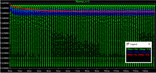
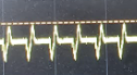
the cable causes SI issue where noise is injected, about 50khz, 200mv P-P


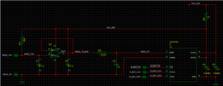
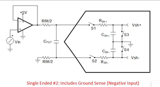
the solution i've come up with is something like this:


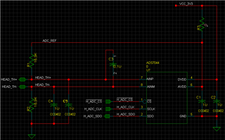
1) I split the pullup into pull up and pull down so that AINM doesn't go below GND, is this necessary? any problems with this?
2) I expect the differential input generally deal with the noise, is this correct?
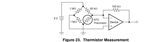
3) I would like to understand the input load of this device, i see in figure 33 the model of the input.  if the input is not changing, is the voltage at Cs+ and Cs- stable, or does initiating a sample cause any load / voltage to change? (i ask because the current through the thermistor is very small,
4) Is this a good solution or can you recommend a better one?
5) i've also added tvs diodes to the th+/- lines as they connect to external connector and wire.
6) i would expect that i do not need C4 & C5, but can add them to avert risk (to appease boss)
7) since this circuit always results in a positive signal, then this is similar to an 11 bit single ended.  i assume that if i sample very quickly, i can accumulate values and do averaging like other ADC to increase the effective number of bits?  or i could replace with
8) a coworker had recommended using an OPA333 to buffer the input signal into a ADS7866 and used an external reference source.  I feel that the solution i came up with is much cleaner, cheaper, and will result in better measurements, but they are more senior and risk averse.  opinion?

Any thoughts and suggestions are welcome.  thank you.

  • Hi WorkerBee,

    I don't see anything necessarily wrong with this implementation, but to me, the simplest and most reliable way would be to filter out the high frequency noise first, since the temperature signal is close to DC, and then buffer the signal with an amplifier.

    Differential measurements attenuates noise that is common to both positive and negative inputs. If the noise you are seeing couples equally to the positive and negative inputs, then it will be attenuated by the magnitude of the common-mode rejection ratio. For this device, the CMRR is -53dB. 

    In this configuration, I don't really expect you to need TVS diodes, since the current should be limited enough by the equivalent resistances of the pull-up/down resistors and thermistor. If an overvoltage condition occurs, the resulting current through the ESD protection circuitry would be limited so as to not damage the device.

    C4 and C5 here act mainly as filter capacitors, as mentioned above. They will filter some of the higher frequency noise while keeping the input steady.

    As you mentioned, since you are using only the half of the total input range, you would effectively be getting 11-bit resolution. The issue with sampling faster is that the sampling switch does inject kickback noise into the input when it closes, and the input needs to settle before sampling to get an accurate reading. The faster you sample, the less time you have for the input signal to settle between conversions. The total RC values of the input also need to be considered, since they prolong settling according to the RC time constant. This is another area where an amplifier helps, in providing a low impedance source to the ADC, enabling you to sample much faster. 

    The first thing I would like to know is whether the noise is indeed coupled equally between the positive and negative sides. Also, how fast are you looking to sample the temperature value? Will you be sampling constantly, or will you be taking one shot every second or 500ms for example?

    You can theoretically improve dynamic performance by oversampling and averaging, but your static performance will not improve, so for a slow-moving signal like temperature, it is better to use an ADC closest  in input range to your output signal. The ADS7042 would be the single-ended alternative to the ADS7044, with an input range of 0-3.6V.

    Regards,
    Joel

  • filtering out the noise is part of the solution, but looking at it differentially would remove it... though i like this idea, just a simple buffer and RC would work too.
    so to keep it simple, i've changed my design:

    requirements, lets just say that i'm looking for the most accurate value i can every 500ms.  the goal is < 1% the 34k is a 0.1%, and since the ADC reference is the same as thermistor, no high accuracy Vref is needed correct?

    So i can sample 1@2hz or 128@256hz in that period and average them.  i assume that i'll get the best results with averaging

    i was trying to understand what kind of a load the sampling represents (#3). 
    for example: LA2518/2528 discharges its sampling capacitor (15pF) to AVDD/2, then connects the switch of 150ohm(typ) for 300ns.  do you have this information for the ADS 7042/7044 ? 

    in my new design, is this ok?  there is so much that could be done, i put in the TLV333 as it was in our system already and seemed to be a good choice, but if you have a suggestion for a different circuit or components please let me know.

  • Hi WorkerBee,

    As mentioned, for an application like temperature sensing, which is relatively stable, oversampling will not improve the static characteristics of the ADC (linearity, offset error, gain error). Oversampling is more useful in improving dynamic performance (SNR/THD) of fast-moving signals, a 10kHz sine wave for example. From my testing, I have seen that the ADS7042 resets the sampling switch to 0V. Because of this, you will have 8.318 RC time constants to settle to 12-bit resolution within the acquisition time of the ADC. Because of this, this sets a ceiling on how fast you can sample, which I calculated to be around 50 Hz with your current RC filter values, assuming a worst-case, full-scale step input. 

    The TLV333 seems like a great choice with its rail-to-rail input/output and 130dB CMRR, much higher than the ADS7044 alone. The circuit you've implemented doesn't look quite right. Since the amplifier has very good common-mode rejection already, there shouldn't be a need for an RC in front of the amplifier. The TLV333 datasheet has a good typical thermistor bridge circuit you can follow. As you get a single-ended output at the end, this seems like the right use-case for the ADS7042 instead. 

    Given that the ADS7042 has AINP and AINM inputs, you can split your current 2.2k ohm resistor value between the two current paths, as seen below. An Rfilt/2 value of 1k ohm seems like a good place to start, with the same 1uF capacitor value.

    The main motivations in going for the ADS7042 + amplifier over the ADS7044 are because the amplifier has much better CMRR than the ADS7044 (53dB vs 115dB attenuation), and that the ADS7042 gives you better effective resolution as you are using more of its input range than you would be using with the ADS7044. If you would like to achieve higher sampling rates, we can adjust the RC filter values and decrease the RC time constant. Let me know what you think of that solution! 

    Regards,
    Joel

  • I have not finished reading your reply, much of it seems like good information.  Thank you for responding to my input sample load question.

    one thing that i question is the comment about having to sample slower due to my large LPF on the pin.  and while what you are saying about waiting several Tau is correct, another factor is how much the input sample affects the external signal.

    Along with the larger Tau, also comes less impact of the sampling effect.  I do not have the math to back it up, but intuitively I would think that at a given sample rate, increasing the capacitance on the signal would not yeild worse results.

    I would think that the size of the R in the RC does have an effect, as the ADC will be drawing some current, and the amount of current through the R will result in a voltage drop. 

    if there were 0 uF cap used, the voltage drop would be captured right away by the ADC, as Cap goes up, the drop lessens, but requires more time to recover.

    so i expect that i calculate the charge consumed by the ADC and average that over the sample time in order to get the impact.  am i off here?  any idea of the math i'm looking for?  thanks.

  • also, the reason i was thinking that averaging would help is that in my experience with the MSPM0, both in the datasheet they say you can get more effective bits when you use averaging, but also as i have one of those on a board, i've noticed that the readings were not as stable as i'd expect and averaging greatly improved the results.

    Also, at first i was looking at using the TLA2518 (so i could read this signal and many others), and many user comments indicated that to get consistent readings they had to use the averaging feature.

    So for these reasons I was expecting that if i wanted to have at least 12 good bits of data (maybe even more effective bits) that I would definitely want averaging.  is this not the reality?

  • I also would like someone to explain why adding signal conditioning helps things.

    with my choice of pullup, a simple resistor divider would use 40% of the ADC's bit space, and has the most bits centered around the temperature range which i'm most sensitive to.  so on a 12bit device, i'm turning it into basically 10.7 effective bits, but no accuracy lost. (just the 0.1% pull up)

    if i add more resistors to put into equations, i may get more effective bits, but the value measured may be off now by another .2% (i didnt check the math on the effect of added resistors, so i could be wrong)

    (assumption) averaging can give more effective bits, without reducing accuracy.  which is why originally i was trying to use just the ADC with no buffer.  as even the buffer would add some amount of error.

    In the current design where we see the noise, TH- is tied to ground and will require a lot of work to remove the connection and see if the noise also would show up on TH- if i used half the resistance on TH- and half on TH+.  since I dont know for sure that the noise is induced on the line and that the same noise would show up on TH-, i shifted my focus away from differential and the assumed subtraction of the noise in order to go with what i know, which is what the noise looks like single ended.

    the reason I was going with the buffer is 1) to improve the ESD protection 2) the ADC will consume some current, if i take the current used from the pullup (34k) it will have a much greater effect and require a MUCH lower sampling rate than if i have it buffered and then go through the RC.  note that filtered results of the noise were reduced to acceptable levels, even at 200ohm-1uF, i just didnt have those resistor values on my board already.

    In the back of my mind, I do have limited space as this is a revision of existing board.  so that may be biasing my views as well.

  • I've dug way into the details to actually calculate all the values and equations and modeled them in ltspice (sorry).
    the calculations, spice, my gut all seem to be in agreement.
    the pullup/drive resistance used combined with the sampling frequency determine the voltage drop.
    I picked a steady state voltage (1.641)
    I used 15pF for ADC sample
    due to the large filter cap, the amount of charge taken by the ADC is negligble
    so Charge taken by a sample is these 2 multiplied
    average current is charge per cycle / period of cycle
    then take this average current and run it through the source resistance. (in my above sch i used 2.2k but for  simulations i was using 1k)
    this results in 1.629 instead of 1.641
    Given a constant R, but changing C of the filter at a broad level you can see that the value of R matters more than C as it affects the signal if you sample too fast...

    as we'd expect the larger cap shows less ripple, but they all converge to the same average voltage.

    now to the question of what the sample looks like, and how each single sample is affected by the filter Cap size:
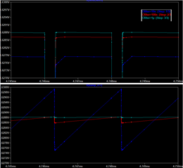
     the bottom is the external pin model, so while the smallest cap recovers quickest, it also drains the fastest.
    so even though all 3 had the same average voltage at the sample pin, the largest cap had the highest sample voltage (closest to the average voltage. (upper image is the sampling cap)

    now that we see the exaggerated effect, lets look at the example that you calculated for...
    i changed the sample period to 198us / 5khz.
    the smallest cap 0.01u, so its well under the recovery time you suggested. we see the smallest cap recover quite well, while the larger cap does not and over time lowers. (but notice how much the smaller cap is affected by the sample.)

    while this looks bad for the larger cap, when we zoom into the last case on the sampling cap inside of the ADC:

    While with 1uF the external signal does not recover, it still has the better sample because its less effected by the sample
    the reason that the signal is not able to recover is not due to the RC time constant, but due to the current draw through the R. The larger cap is simply decaying to the most accurate value.
    My conclusions:
    1) more C is always a better sample of a static signal
    2) sample time is actually limited by the max signal voltage and R.
    3) RC does come into play when trying to react to the signal's rate of a change, but not sample rate.

    by the way, the suggestion of using half the filter resistance on + and -, if the cap does get set to 0V before a sample, this resistor is not effected by the sample effect, so you end up getting a higher sample rate due to the smaller R from the sample.

    so this answers my first response, unless you disagree or have something to add.
    my other 2 response questions are still open (summary of above, open questions)
    -averaging and effective bit rate / accuracy, is this a valid way to remove noise and get more effective bits, more precise readings?
    -signal conditioning, is it worth it?  the circuit you recommended basically puts an offset and scaling factors to make more use of bits... i dont see how this makes things more accurate, it seems to make it less... both of the offset resistors add an offset error, and the scaling adds in a scaling error, and the only thing you get is 1 more effective bit, it doesn't seem worth it, especially if averaging can get more effective bits.

  • Hi WorkerBee,

    Sorry I couldn't get to you last week. You've done a great job of digging into this yourself, but let me cover a few points you made. 

    I should clarify the benefits of oversampling. Oversampling improves effective number of bits (ENOB) by means of noise reduction (improving SNR). Given a DC signal, oversampling will decrease the variability in your measurement. This is important if errors from uncorrelated noise (white noise) are your limiting factor, but this does not determine the actual accuracy of the ADC, where linearity is more important. For deeper discussion of that, I would direct you Part 1 and Part 2 of the ADC Accuracy E2E blog posts. I'd like to hear any feedback or lingering questions you have from those posts, and hopefully we can help clarify them in future content. I would also recommend looking at the "Resolution-Boosting ADS7138 Using Programmable Averaging Filter" application brief, which has good information related to oversampling, not necessarily specific to the ADS7138. Hopefully these answer your questions regarding oversampling.

    Maybe I misled you in stating that the smaller RC is always preferable. In your case, it is better to have a larger capacitance if you are sampling a slow moving signal on a single channel, and you are only sampling once in a while. Something to consider is that the first conversion on power-up should consider the time it takes for the capacitor to reach the final value. The Driving SAR ADC without amplifiers TI Precision Labs video actually does a great job of explaining what use cases you can get away with without an amplifier, and the calculations necessary to safely make design choices.

    After properly calculating, the ADS7044 common-mode rejection ratio does drop the amplitude of the 200mV noise you see to under 1 LSB at 3.3V AVDD, and the low-pass filter in front of the ADC should attenuate it even more. Given that, I do agree that you can achieve more noise-free bits from averaging. Offset errors can usually be calibrated for if need be, but realistically, these errors aren't often the limiting concerns when discussing 12-bit ADCs or lower. In your case, considering other errors introduced , signal conditioning may not be worth it.

    Regards,
    Joel

  • You did not state that smaller RC is always preferable.
    You stated:
    Because of this, you will have 8.318 RC time constants to settle to 12-bit resolution within the acquisition time of the ADC. Because of this, this sets a ceiling on how fast you can sample, which I calculated to be around 50 Hz with your current RC filter values,

    and in a different thread:
    It's important to keep in mind that to reach nominal resolution with an ADC, you need to allow for more acquisition time than ln(2^n)*R*C, where n is the resolution of the ADC in bits. ln(2^n) gives you the number of RC time constants you need to wait before the signal is fully settled. The result you get is in seconds.

    the RC affects how quickly a change in signal is seen at the input to the ADC.  in both cases though you talked about taking RC into account with sample rate / acquisition time.  This seems wrong / missleading. 

    there are 2 ways i can interpret what you said,

    in the input-centric way, we must wait a period of time after the input signal changes until we sample. The signal is never settled as its a temperature and there is no point at which we can say its done changing and then sample. 

    the other way is related to the ADC sample affecting the signal and limiting the sample rate.  as i showed, sample rate is not limited by the RC, a larger C actually helps the sample which is contrary to limiting sample speed based on RC.
    I also pointed out that the R affects the signal because of the average current draw across it, dropping the measured value.  in neither way does the time constant say anything about the sample rate.  the max sample rate only depends on the signal voltage, the input capacitance, the R of the RC, and the max allowable voltage drop of the signal.