This thread has been locked.

If you have a related question, please click the "Ask a related question" button in the top right corner. The newly created question will be automatically linked to this question.

ADS1261: 2 wire excitation mode problem

Part Number: ADS1261

Tool/software:

Hi all,

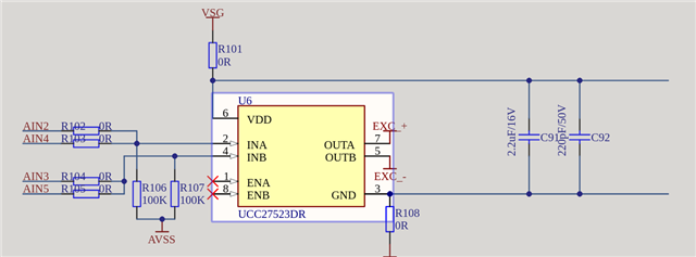
We are currently experimenting a strange issue with the 2 wire excitation  mode. Our schematics, is exactly the same as the one in the EVM (with the exception that we use the UCC27523DR)

The custom pcb is for a 6 axis load cell, and the acquisistion is roughly like this:

  1. Setup the DRDY pin as interrupt mode
  2. Configure the ADS (PGA on, gain 1, default for all the other registers)
  3. Start continuos conversion at 40 ksamp/s
  4. Everytime we receive an interrupt, we read the value and switch to the next channel and so on

The acquisistion is differential: basically one channel of the load cell with an "hardware" offset.

This works very well in NORMAL and CHOP mode, but when we try to setup ACX mode (to see the effect on the temperature), the acquisistion system seems to saturate somehow. I have made some acquisistion so to help better to understand the problem.

Photo 1: INA and INB (equal to AIN2 / AIN3) at 40 ksamp/s

Photo 2: ECX+ and ECX- output

Photo 3: Acquisistion when the gain is set to 1 (status reg = 0x0D, reference low alarm)

Photo 4: Acquisistion when the gain is set to 32 (status reg = 0x3D, reference low alarm, pga high / low alarm)

The ADS1261 is powered with a single supply of 5V (no bipolar, but AVDD = 5V and AVSS = GND).

What we noticed is that if we switch the reference from the default one (AVDD / AVSS) to internal reference positive / negative, the measure is not saturating always, but it has some spikes in the measurement (see photo below):


Can it be that for ACX mode we need a dual supply voltage?

  • Hi Elia Pellegrino,

    If you slow down the ADC data rate, does the situation improve?

    In the image where you are using a gain of 32, the average value you are measuring looks to be around -0.65785V (not sure? the x-axis is not labeled) and the signal does not appear to be saturating or swinging wildly from positive to negative. Would you consider this to be "good" data?

    Can you provide a complete schematic so we can at least see the ADC circuitry, the input circuitry between the ADC and the terminal blocks, and the ACX circuitry?

    Can you also provide the register settings?

    -Bryan

  • Hi Bryan,

    If you slow down the ADC data rate, does the situation improve?

    No, I have already tried to slow it down to 14.4 ksamp/s, but the situation is the same.

    In the image where you are using a gain of 32, the average value you are measuring looks to be around -0.65785V (not sure? the x-axis is not labeled) and the signal does not appear to be saturating or swinging wildly from positive to negative. Would you consider this to be "good" data?

    No, I cannot consider it as good data, as the values are all the same and they cannot change if apply some load to the load-cell. Yes sorry for the missing label, y-axis is Volt, while x-axis second.

    Can you also provide the register settings?

    For sure, this is our register settings:

    Reg Name Value
    ID 0x0081
    STATUS 0x0001
    MODE0 0x0083
    MODE1 0x0041
    MODE2 0x0030
    MODE3 0x0040
    REF 0x0005
    OFCAL0 0x0000
    OFCAL1 0x0000
    OFCAL2 0x0000
    FSCAL0 0x0000
    FSCAL1 0x0000
    FSCAL2 0x0040
    IMUX 0x00FF
    RESERVED 0x0000
    PGA 0x0000
    INPMUX 0x0006
    INPBIAS 0x00A3

    Can you provide a complete schematic so we can at least see the ADC circuitry, the input circuitry between the ADC and the terminal blocks, and the ACX circuitry?

    Yes, find attached a simplified schematics of our board:
    ADS1261 Report.pdf

    Moreover, I do not know how, but it seems that after using the ACX mode in this way, the ADS seems to not be responding anymore to the SPI command: can it be that it has been damaged by an high voltage outside its operating condition?

    Thank you very much for your help,

    Elia

  • Hi Elia Pellegrino,

    Thanks for providing the requested information

    None of the supply nets have voltages, they just say e.g AVDD, AVSS, etc. Can you provide the ADC supply voltage levels as well as the excitation voltage levels (VSG+, VSG-)?

    Can you also try slowing the ADC down much more, like 100SPS? I understand this might not be how you want to operate the ADC but this is just a troubleshooting step

    -Bryan

  • Hi Bryan,

    Yes you are right sorry. I cannot show you the power input stage, but:

    • AVDD: 5 V
    • AVSS: GND
    • DVDD: 3.3V
    • VSG+ / VSG- comes out from a switch and go directly for "powering" the load cell (as you can see in "Input Stage / Load cell"). When using the 2 wire ac mode, we switch it manually to EXC+ / EXC-

    Can you also try slowing the ADC down much more, like 100SPS? I understand this might not be how you want to operate the ADC but this is just a troubleshooting step

    Yes, I can, but I am bit afraid of breaking another ADS, as it seems it already happened with 2 of them. I will have a try on friday and I keep you posted.

    In the meantime, do you have any clue of what can be the problem?

    Thanks,

    Elia

  • Hi Elia Pellegrino,

    You mentioned "high voltage" in one of your previous posts. What is the voltage level you are referring to, and where does this come from in your system?

    Can you tell me what is the actual voltage level for VSG+/VSG-?

    Why do you have AVSS and GND nets if they are the same potential? How are these connected on the PCB?

    -Bryan 

  • Hi Bryan,

    You mentioned "high voltage" in one of your previous posts. What is the voltage level you are referring to, and where does this come from in your system?

    Can you tell me what is the actual voltage level for VSG+/VSG-?

    When using the 2 wire excitation mode, we switch the switch S1B, so that VSG+/VSG- is equal to EXC+/EXC-. The output of this are shown in the figure above. So, we are basically exciting our load cell with a differential voltage of VSG+ = 5 / VSG- = -5, because the difference of (VSG+ - VSG-) is given by a difference of a (square wave - (-1*square wave)), as you can see in the figure above. This is where my concern lives: given the fact that the load cell is basically (in simple term) a resistor, we are giving as analog input a voltage that is below AVSS, when the excitation voltage is -5V. Am I missing some points on how 2 wire excitation works?


    Why do you have AVSS and GND nets if they are the same potential? How are these connected on the PCB?

    They are connected together through a net tie, so they are at the same potential.

    Thanks,

    Elia

  • Hi Elia Pellegrino,

    The applied voltage is not negative with respect to ground during AC excitation, it just has the opposite polarity. So you are applying 5V to the top of the bridge and 0V to the bottom of the bridge during the first phase, and then you are applying 5V to the bottom of the bridge and 0V to the top of the bridge during the second phase. So this should not be an issue. But when you mentioned "high voltage" it wasn't clear to me what the excitation voltage actually was

    Have you tried slowing down the ADC? My originally thought is that you are seeing settling issues because the excitation polarity is switching so fast. The RC circuit you have on the ADC inputs needs to settle every time the excitation voltage switches, and 40kSPS might be too fast

    -Bryan

  • Hi Bryan,

    Yes, I tried but nothing change. And again, after some time of using with acx mode, the chip seems not to be responding any more

  • Hi Elia Pellegrino,

    There is no obvious reason why the AC excitation circuit would cause the ADC to break, unless you are somehow overdriving the ADC pins. But what you have described so far does not indicate that that is the case

    Are you able to get an ADS1261EVM so you can start with a known good board that already has a working AC excitation circuit? This will at least give you a place to start

    Then you can wire in your controller to the EVM so you can check that your code is correct. You can also wire in your AC excitation circuitry (bypassing the circuitry on the EVM) to see if that works correctly. And so on, checking the individual components to see where the issue is

    This sounds a bit like it could be a grounding issue, but without have the board in front of me it will be hard to diagnose remotely. So getting an EVM seems like the next best option

    -Bryan

  • Hi Bryan,

    Thanks, I will perform this tests during these days and I will let you know something!

    Elia

  • Hi Elia Pellegrino,

    Thanks for the update

    -Bryan