This thread has been locked.

If you have a related question, please click the "Ask a related question" button in the top right corner. The newly created question will be automatically linked to this question.

ADS1261: Handling >5v excitation properly

Part Number: ADS1261

Tool/software:

Hello,

I am reading the TI application note "A Basic Guide to Bridge Measurements".

We have an application which requires 10V excitation. We have a bipolar +-2.5V source, and can get a bipolar +-5v source as well.

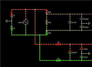
Obviously, the part can only handle 5v on REFP-REFN, and the suggested solution from the app note seems to be a resistor divider.

I have a few concerns:

  1. We have customers using our product with long wire runs, is there reason to be concerned about the resistor divider being in place making this situation worse for excitation used as reference? For example, I can imagine that at some point the resistance of the leads gets close to the resistance of the divider.
  2. I would like to know if it's a good idea or possible to perfectly compensate the RC filter network after the resistors so that the bandwidth is identical to the signal channels.
  3. What magnitude resistors would you suggest?
  4. It seems we lose the ability to do burnout current sources to test connections if we buffer anything (though, I suppose we could excite the bridge ourselves).

Is there any solution for AC excitation of bridge sensors that allows for 10v excitation without being overly complex or with these pitfalls?

  • Hi Alex,

    Welcome to the TI E2E Forums!

    1. Yes, six-wire measurement is an ideal solution for the measurement with long wires. It can ensure that the ADC VREF is the same as the voltage driving the bridge and improve overall system accuracy compared to the four-wire bridge as you can see the details from the application note.

    2. I'm not exactly sure what you mean here. You can see the guideline for the component selection here: [FAQ] Delta-sigma ADC anti-aliasing filter component selection. Also, I would recommend that the signal inputs and reference inputs can be designed with matching filters. This ensures that the excitation voltage noise will be common to both inputs (across the frequency spectrum) and results in better noise cancellation.

    3. One possible solution to detect whether the connection is disconnected or not is using pull-up/pull-down resistor on the input.

    There are two things you have to consider for 10V excitation:

    The ADC's input common-mode voltage

    Most ADCs including ADS1261 have a measurement range from 0 to 5V for an analog supply of 5V. With 10V excitation (referenced to ground), you will have a common-mode voltage of 5V (mid-excitation supply). This requires a level-shifting the reference or signal voltages to meet the ADC input limitations as most ADCs only support AVDD ≤ 5 V. In this case, you have to use an external instrumentation amplifier (INA) in front of a gainless ADC to amplify the bridge signal and properly set the amplifier output common-mode voltage  into the common-mode range of the ADC.

    The ratiometric reference voltage

    For 10V excitation, you'll also need to divide down the excitation voltage with a resistor divider before routing it to the ADC, it will not be truly ratiometric as there will have noise and the drift of the resistors, and if you use a buffer there will be additional noise, offset and gain drift of the amplifier.

    If you could use 5V for your bridge excitation, you can just use an ADC with an integrated PGA, like ADS1261. This will greatly reduce the complexity and cost while increasing the level of precision.

    Except the application note "A Basic Guide to Bridge Measurements", you can also check Reduce Bridge Measurement Offset and Drift Using the AC Excitation Mode in the ADS1235 and ADS1261

    BR,

    Dale

  • What I mean by 2. is - if we put a resistor voltage divider in front of the differential filter - it acts to change the R in the network which changes the filter response. For example, the 1k resistor feeds a 100nF and 10nF capacitor network on the bottom, and the voltage divider feeds a 6.25nF and 625pF in this simulation. I'm just confirming this is the expected thing to do.


    Or, should I select the resistors such that the impedance into the filter is the same (1k in this case)?

    From the app note:

    > Keep the nominal resistance value low to limit thermal noise. As an example, a 1-kΩ resistor at 25°C and 1-kHz bandwidth contributes 128 nVRMS of noise.

    > Additionally, a buffer might be required depending on the impedance of the ADC differential reference inputs.

    This seems a bit tricky, using really low resistance values means that the leads from the excitation or 6-wire sense lines form a leg of the resistor divider. For example, 2 ohms of resistance is potentially 0.2% shift. I am also not sure at which point a buffer is necessary, I'm not entirely sure how to interpret the figures for the voltage reference inputs:

    How is absolute input current +-250nA when there is an "input current vs voltage" figure of 15nA?

  • Hi Alex,

    I will look into the details and get back to you next week.

    BR,

    Dale

  • In what conditions would you recommend using a buffer?

  • Hi Alex,

    1. You example already showed the reason why you need a buffer to isolate the resistor divider and RC filter.

    2. "Keep the nominal resistance value low to limit thermal noise. As an example, a 1-kΩ resistor at 25°C and 1-kHz bandwidth contributes 128 nVRMS of noise."

    This is a tradeoff when selecting in terms of noise and bandwidth.

    3. "Additionally, a buffer might be required depending on the impedance of the ADC differential reference inputs."

    If you use a resistor divider on the external reference and also the impedance of the ADC reference input is not high enough, the ADC reference input will definitely affect the impedance of your resistor divider, so you need an buffer to isolate your resistor divider and the ADC reference input under this condition.

    I hope my explanation is helpful for you to understand.

    BR,

    Dale

  • Could the current specification be clarified for the ADS1261 in my screenshot, to help better design the circuit? Are all the specifications except the impedance single ended? I.E. REF_p will have 250nA + 15nA/V + 0.2nA/C, and then the same for REF_n? 

  • Hi Alex,

    Your understanding is correct. My colleague (Bryan) recommended some solutions with ADS1261 or other ADCs for 10V excitation, please see the details in  ADS1261: Input Voltage Range for Strain Gauge.

    BR,

    Dale