This thread has been locked.

If you have a related question, please click the "Ask a related question" button in the top right corner. The newly created question will be automatically linked to this question.

ADS1261: Input Voltage Range for Strain Gauge

Part Number: ADS1261
Other Parts Discussed in Thread: ADS125H02

Hi,

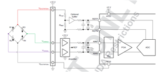
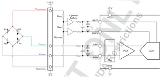
I want to measure strain gauge sensor fed with 10V excitation. As far as I understand 10V value exceeds absolute voltage and common mode range of ADS1261. How can I use ADS1261 for this purpose? and is radiometric voltage excitation possible with this ADC?

  • Hi Ismail,

    You are correct that the typical output of a 10-V excited bridge would violate the input range on the ADS1261. Therefore, you would need an external amplifier / INA to level-shift the bridge common-mode, typically to mid supply (AVDD/2). For the reference, you could do something similar, or you could use a simple resistor divider as shown in the first image below. This configuration with the two resistors offers the closest approximation to a ratiometric reference. However, any mismatch in error between the amplifier stage on the input and the resistors on the reference will reduce the ratiometricity of the measurement.

    You could also consider using the ADS125H02, which can accept up to +/-15V directly using a +/-18V supply. Then you would not need the signal conditioning circuitry on the ADC inputs, though you would still need the resistor divider for the reference.

    Another option would be to bias the bridge with +10V and -5V, instead of +10V to GND. This bipolar, asymmetric supply puts the bridge output common-mode voltage at 2.5V, so you would not need the signal conditioning circuitry on the ADC inputs, though you would still need a resistor divider for the reference. This is shown in the second image below. This also assumes your bridge or load cell can support an excitation voltage of 15V.

    Ensure that in all cases you use precision resistors for the reference divider. Any gain error or drift in these resistors directly shows up in the reference voltage, but not in the input, reducing the effectiveness of the ratiometric reference.

    High voltage unipolar supply (+10V)

    High voltage bipolar supply (+10V, -5V)

    -Bryan

  • Hi Bryan,

    Thank you for your detailed answer and helpful recommendations. Most probably, I'm going to use bipolar supply solution but I should ask why you have used 15V bridge supply. Because bridge voltage should be 10V and we can use +7.5V -2.5V or +6V -4V rail voltages in order that maintain the common mode voltage in correct range.

  • Hi Ismail,

    Yes, you are correct, something like a +7.5 / -2.5V supply would work as well. That image is taken from an application note that we are going to release soon that covers this topic, and I just didn't change the values.

    Take care with a +6V / -4V supply however, as the bridge common-mode voltage will be around 1V in that case. This is much closer to the input limitations on the ADS1261 PGA (and most general INAs), which prefers a voltage around AVDD/2 as I mentioned. You can use our ADS1261 calculator tool to help visualize if your settings will work: https://www.ti.com/lit/zip/sbac200.

    The image below shows this tool in operation. As you can see, a 10mV signal centered around VCM = 1V still enables the maximum gain of 128. However, a larger input signal will reduce this range. Feel free to use this tool to check if your system parameters will work.

    -Bryan

  • Hi Bryan,

    This tool is very useful, thanks. My last question is about reference voltage. According to datasheet, there is a limit for absolute reference voltage depending to analog supply voltages. Should I also shift the voltage level with reference buffer, is it necessary?

  • Hi Ismail,

    Yes, as shown in the images from my first post, the reference voltage is divided down into the input range of the ADC using a resistor divider. You might consider adding a placeholder for a buffer between the resistors and the ADC VREF inputs, though I would assume the ADS1261 internal VREF buffer should be sufficient (specified at 30Mohm). The resistors should be high accuracy, low drift, as any error in the resistors directly causes a measurement gain error.

    You could also use an amplifier to level-shift the signal. Again, choose high performance components to maintain high measurement accuracy.

    Let me know if this answers your question.

    -Bryan

  • Actually I want to know whether voltage level of reference input (relative to ground) in correct range or not? Maybe if I use common mode filter, this voltage level can be exceed the absolute voltage levels while capacitors are charging. It's a transient behavior but I'm not sure. Therefore, probably we should shift the reference voltage with an opamp.

  • Hi Ismail,

    Yes, this is possible in the bipolar, asymmetric supply situation. I would recommend targeting a voltage that is slightly less than the full range of the ADC input. So, for example, 4.9V for the ADS1261 where the maximum VREF voltage can be 5V. You would then scale the resistor divider accordingly to generate these voltages based on the value of the (+) and (-) excitation voltages.

    Our application report on this topic should be released in the next few weeks. I will post a link to this thread when it is live on TI.com.

    -Bryan

  • Hi Ismail,

    I just wanted to let you know that the application note on bridge measurements has been released: https://www.ti.com/lit/pdf/sbaa532

    This should help support some of the additional questions you may have. I hope all is going well with your design

    -Bryan

  • Hi Bryan,

    Thanks for your helpful support and sorry for late reply. This app note is great. It includes very detailed and easy to understand explanations, my schematic design is finished but I will check it again after I completely read this new app note.