This thread has been locked.

If you have a related question, please click the "Ask a related question" button in the top right corner. The newly created question will be automatically linked to this question.

ADS124S08: Measuring four 2 wire RTDs with ADS124S08

Part Number: ADS124S08

Tool/software:

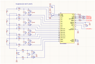
Hello, I have constructed the following circuit with a ADS124S08 to measure four 2 wire RTDs.  However in my testing, the circuit doesn't work. With IDAC1 set to 1000uA and a 1kohm resistance for an RTD, the measured voltage with a multimeter across the rtd resistor (S1) is 0.223V and the measured voltage across RREF (R146) is 1.48V.  The output code of the ADC is 2983394, for a calculated RTD resistance of 711 ohms. Can anyone help me diagnose the issue and redesign my circuit?

I think maybe the current from the idac is taking an alternate path, perhaps through the disconnected analog inputs.

There is a thread with some discussion here: https://e2e.ti.com/support/data-converters-group/data-converters/f/data-converters-forum/571980/ads124s08-how-to-measure-four-3-wire-rtds  that relates, my design is somewhat different though, because I am measuring 2 wire RTDs instead of 3 wire.

  • I just tried removing S2, S3, S4, R140, R142, R144.  However the measurements are still the same.

  • I should also specify that I am attempting to measure a PT1000 rather than a PT100 that the circuit is designed for. Perhaps RREF is too large?

  • Hi James MacLean,

    What is the actual RTD resistance you are trying to measure? Can you try similar measurements with a fixed resistor value to rule out any issues with the RTD?

    I assume you are only turning 1x IDAC on at a time? For example, you are turning on IDAC1 and setting it to output 1mA on AIN0. This current should flow through S1 only, then through R146, and then to ground. When you do this, you are measuring the values you mentioned above (~0.2V across the RTD, ~1.5V across RREF) - correct? And of course, IDAC2 is disabled during this measurement

    Also, ensure that the REFP0 buffer is on and the REFN0 buffer is off (these are the default settings). You should also remove C16 and C18 from your circuit, and replace R147 with a 0 ohm resistor. 

    -Bryan

  • Hi Bryan. Thanks for the response. I figured out the issue. The pinout was backwards on the connector for my RTD. It works now. The fixed resistance I am trying to measure is 996 ohms. I am now measuring about 999 ohms.

    So I am very close but still too inaccurate.  I am hoping calibration will fix the issue. All four channels measure about 999.

  • Ok, so I figured this out too. I was measuring my resistance with a handheld meter. I switched to a more accurate Keithley with a 4 wire measurement. The actual resistance of the test load is 998.67 ohms.  So there is only a 0.5ohm offset, which I have measured as being the resistance of the cables/connectors/traces. So it is pretty much exactly accurate.

  • Hi James MacLean,

    I'm glad this was resolved, thanks for posting the solution

    -Bryan