This thread has been locked.

If you have a related question, please click the "Ask a related question" button in the top right corner. The newly created question will be automatically linked to this question.

ADS114S08: PGA Pin Setup

Part Number: ADS114S08
Other Parts Discussed in Thread: ADS124S08,

Tool/software:

Hi,

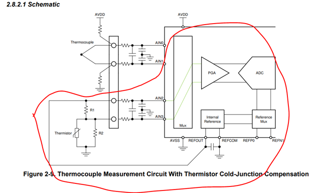
My customer is currently using this device to measure thermistors, however, we've noticed this post where TI is advising against this setup:

https://e2e.ti.com/support/data-converters-group/data-converters/f/data-converters-forum/802426/ads114s08-cannot-use-the-same-pin-for-the-pga-input-and-the-excitation-current-source/2969118?tisearch=e2e-sitesearch&keymatch=ADS114S08%25252520IDAC

Could you elaborate why this is not encouraged? Thanks!

  • Hi Abigail Leonardi,

    Firstly, can you please help us track this opportunity by providing the customer name in the Notes section of the Thread Tracking Toolkit above the thread title?

    The discussion in the post you highlighted was mainly related to a temperature measurement with RTDs that require a current excitation from internal IDAC source on ADS124S08, they were talking about connecting the IDAC to the same signal sensing pin or using a dedicated pin for sending IDAC current to the external RTD sensors. 

    A typical thermistor measurement would be designed using the REFOUT of the ADS124S08 to bias the thermistor, this is called as voltage excitation, then measure across the thermistor as shown in the circuit that is circled below. In this case, the REFOUT from ADS124S08 is used to bias the resistor divider, and the ADC measures either the top (differential) or bottom (single-ended) resistor. You would then use the ADC's internal VREF as the measurement reference. This will be a ratiometric measurement, since the thermistor output voltage will scale with the ADC reference voltage. This is important as measurement excludes the drift of the excitation source. The VREF on the ADS124S08 can be driven up to 10mA, so it should be more than sufficient to bias multiple resistor dividers/thermistors.

    It is also possible to use an current excitation, but the current generally needed is pretty low (~10uA) because the NTC resistance can be very high (nominally maybe 10k, and then can increase to 100kohm at the temperature extremes), so the voltage-excited circuit as explained above is more common.

    BR,

    Dale

  • Hello Dale,

    I am the customer who initially sent the email to Abigail regarding our design. On most of our other designs, we do typically use the voltage divider method for thermistor measurements. For the design in question, however, our board space is somewhat limited (15mm x 54 mm) and we are trying to minimize our usage of external support circuitry such as reference resistors, MUXes, etc. To this end we just have each thermistor connected to its own pin on the ADS114S08 (7 thermistors for 7 ADC pins in all) and the other end of each 2-lead thermistor is connected to AVSS. Then for each thermistor we configure the ADS114S08 to output current on the thermistor pin via the IDAC, and then take an ADC reading on that same pin.

    This method of outputting IDAC current and doing an ADC measurement, both on the same ADC pin, seems to work well enough so far, but after reading E2E I saw the post Abigail linked that discouraged using the same pin for both IDAC current and ADC readings and to instead have the IDAC and voltage measurement on different pins. The specific quote from the post is "Although it is theoretically possible to drive current out the same pin as is being measured it is often impractical to do so. In fact we discourage this type of usage due to noise concerns."

    I was wanting to know what TI's specific concerns are about using the ADS114S08 the way we are trying to use it. This sensor is intended specifically for forestry applications and industrial levels of electrical noise are not expected; 50/60 Hz line noise is also not common. 

  • Hi Christopher,

    Thank you for jumping in and letting me know the information.

    The multiplexer switches usually have an on resistance from tens to hundreds of ohms. The IDAC inside the ADC is routed through the multiplexer switches, then you have to live with that additional voltage drop because of the resistance on the multiplexer switches. This is not a specific concern, it will just lead to an error because of the voltage difference like the customer mentioned in the previous post.

    I understood the limit you have to use the current excitation instead of the voltage excitation in your design, your circuit worked well probably because the voltage drop is small and neglectful to your accuracy requirement. If the impact is obvious in your other design in the future, you may do a calibration to calibrate out the voltage difference in your software, or use a dedicated analog input pin as the IDAC out to externally route the current to the appropriate thermistors (this is the best solution).

    BR,

    Dale

  • Thank you Dale. We will work to determine how much error we introduce and whether we can fit an external MUX for routing the IDAC current. I just wanted to make sure we didn't have some terrible measurement faux pas in the way we were doing it now.

  • Hi Christopher,

    Understood. I'm going to close this post, please start a new thread if you have any questions in the future. Thanks.

    BR,

    Dale