This thread has been locked.

If you have a related question, please click the "Ask a related question" button in the top right corner. The newly created question will be automatically linked to this question.

FDC1004: FDC1004 Drift Over Time

Part Number: FDC1004

I'm having a similar issue as the person on this post regarding drift on the FDC1004 readings:

https://e2e.ti.com/support/data-converters-group/data-converters/f/data-converters-forum/727882/fdc1004-drift-on-environmental-reference-electrode?tisearch=e2e-sitesearch&keymatch=FDC1004%25252520drift#

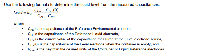
My question relates to the last post in the thread, where the question was asked if the environment reference and liquid reference sensors are identical in size - and in my case, the answer is no.  I'm wondering what the implications are of them not being the same size - as I am using the formula below:

Using this equation, my level trends downward by several percent over the course of a couple of hours. 

Thanks!


  • Hi Eric,

    Yes, the environmental and liquid reference need to be the exact same size.  If they are not, your denominator will be changing the level result in a way that is not intended since they are not symmetric.  If you use the formula without using the environmental sensor, do you also see the drift?

  • Eddie,

    Our application involves 2 sensors using OOP measurements as the liquid level application note shows.  The sensor is designed to detect a target moving over the pair of sensors. 

    One sensing element pair is small, and the passing object will completely cover this element when sliding over it.  The larger main sensing element pair will be partially covered when the object moves over the sensor.  In this way, the smaller sensor can serve as the reference environment sensor when no object is present, and reference 'liquid' when the object is completely covering it (by measuring the periodic peak in the signal).  The larger sensor pair is used to measure the Clev(0) when the signal is at a minima, and Clev when a peak is measured.  Overall the system is working very well, but there is some drift over time which I'm trying to minimize.  I'll be redesigning the sensor soon for some significant mechanical changes to the assembly, so I want to optimize the sensor design if possible!

    Thanks!


  • Eric,

    From your image, it appears that your two small sensors are the same size.  Typically, the level electrodes should be below the reference environment electrodes as shown below.  You do not want the liquid to contact the reference electrode, but in your use case, your layout may be okay since it sounds like you are not actually measuring liquid.  

    https://www.ti.com/lit/ug/tidu736a/tidu736a.pdf 


  • Eddie,

    That is correct - the liquid reference sensor and environmental reference sensor are one in the same, it's just a matter of measuring the min and the max of those signals over 1 period to determine what to use as the 'liquid' reference (max) and environmental reference (min).  With those two using a common sensing element, the equation above should still be applicable as I understand it.  The fact that the environmental sensor is smaller only affects the output scaling, but should still minimize any drift that may be happening.  

    Thanks,

  • Thanks for the information Eric.  Let us know if you have other questions.