This thread has been locked.

If you have a related question, please click the "Ask a related question" button in the top right corner. The newly created question will be automatically linked to this question.

ADS7924: Issue With Manual Scan Mode

Part Number: ADS7924

Hello,

We are using ADS7924 for data conversion. We have Voltage(0V-3.3V) and Current inputs(4mA - 20mA) given to different channels of ADS7924. I want to use Manual Scan mode in my application but I am facing issue with Manual Scan Mode. I need help regarding the same.

The ADC Channels are configured as Ch1 - Voltage1, Ch2 - Current1, Ch3- Voltage2, Ch4- Current2. 

During testing we have given current input to ADC Ch4, remaining channels left open. And We have set mode to Manual Scan Mode and Channel Selection is set to 4 i.e. We have written 0xCB to 00h register. During this configuration we are getting less fluctuations in ADC output. But if I write 0xC8 to 00h register(Manual Scan mode with Channel Selection set to 0), we are getting more fluctuations in ADC output. Why is the channel selection causing issue in our ADC readings.

We have set 50 Micro Seconds as ACQTIME. And we have a 500miliseconds timer configured to read all channel ADC data continously. After reading all the channels data, we are trigger manual scan at the end. So again after 500ms only we will initiate the read and so on.

Please suggest us which channel will be more efficeint for our application.


Thank You.

Regards,

Balaji

  • Hi Balaji,

    Do you have any logic analyzer captures you have taken of the I2C lines? Can you share a schematic of the ADC input circuit?

    Can you also explain more on what you mean by channel fluctuations? What value do you expect, and what value are you getting?

    Regards,
    Joel

  • Hi Joel,

    Thank You for the response.

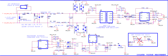
    Please find the ADC Input Circuit(Voltage and Current) and ADC schematic screenshot. 

    Currently I don't have logic analyser captures of I2C lines. I will provide them once we capture.

    Channel fluctuation means, If applied input current is 10mA(to ADC Ch3) and register 00h is set to 0xCB. We are getting ADC Ch3 output varies between 9.95mA and 10.05mA. But If register 00h set t 0xC8 means then ADC Ch3 output varies between 9.8mA and 10.15mA.

    So my doubt is, why does 00h register setting affecting the accuracy/precision of the adc conversion?

    Thank You.

    Regards,

    Balaji

  • Hi Balaji,

    Can you clarify how you are measuring the current?

    0xCB and 0xC8 both select manual-can mode, but 0xCB selects channel 3, while 0xC8 selects channel 0. 

    In that case, you might be seeing more fluctuations when the channel is off (0xC8) because there it is terminated to a high-impedance/floating node. It might be picking up more ambient noise or leakage currents. It could also be that the changing load at the INA output causes the output to swing more from the expected value.

    I don't expect this to be too much of an issue if it is not picked up by the ADC during sampling. Are there other system considerations as to why this might be an issue?

    Regards,
    Joel

  • Hello Joel,

    Sorry for the late response.

    As our input ranges from 4mA to 20mA, even 0.1mA variations are considered as incorrect values. So because of that we wants to achive more accuracy. Currently we are working with Manual Single mode only, where for every 10 miliseconds we are initiating data convertion for all 6 channels followed by a 2ms delay and reading all 6 channels converted data. With this method we are able achive better accuracy compared to manual scan mode. 

    We wants to use Manual Scan mode instead of Manual single mode but we are getting more varations in the output.

    Regards,

    Balaji TS

  • Hi Balaji,

    If the error seems to improve after adding delays between conversions, that would point to this being a settling error. Is it possible to rework the RC filter before the ADC input, after the INA? At the moment it looks like the INA is directly driving the ADC input, which could explain the errors. 

    The RC filter at the ADC input is important to help supply charge quickly to the sampling capacitor of the ADC, and maintain stability. I can help provide further guidance into selecting these values. I also recommend the TI Precision labs videos on driving a SAR ADC (link).

    Regards,
    Joel

  • Hi Joel,

    Doesn't the RC filter cause delay? With RC flter at input side, can we detect sudden changes at the input (without any latency)?

    Regards,

    Balaji TS

  • Hi Balaji,

    So long as it is properly sized, it will not cause a delay. Keep in mind the ADC is sampling at discrete periods in time, so a phase shift does not matter so long as it is smaller than the time between conversion.

    To be more specific, the RC filter must be sized so that the voltage at the input of the ADC settles within 1/2 LSB of the input signal. ln(2^(n+1)) models the number of RC time constants a signal needs to settle given a full-scale step input.

    For example, for a 12-bit device, ln(2^(12+1)) is equal to 9.01. Therefore, to ensure full accuracy conversions, the RC values must be selected so that 9.01 * RC is less than the acquisition time of the ADC. Additional input resistance and capacitance also contributes to the R and C values, so high output impedance sources must be carefully designed around. 

    Any perceived delay is considered a settling error, which I suspect is what the issue may be in your case. the experiments suggested above should give some more information.

    Regards,
    Joel

  • Hi Joel,

    Thank You for the clarification. We have considered of adding the RC filter before the ADC input in the future designs. So in future if any help required during designing means we will ask a new question.

    Thank You.

    Regards,

    Balaji TS