This thread has been locked.

If you have a related question, please click the "Ask a related question" button in the top right corner. The newly created question will be automatically linked to this question.

AMC3306M05-Q1: SDFM Data Glitch Occuring

Part Number: AMC3306M05-Q1
Other Parts Discussed in Thread: TMS320F28379D, , TIDA-01606, AMC3306M05

Hi All,

I am reaching out because we are using three of the AMC3306M05-Q1 similarly to the TIDA-01606 in terms of hardware. This specific part is being used with a shunt to measure the AC current flowing through a 2mOhm resistor on each phase. We are using the TMS320F28379D to decode the SDFM using a Sinc 2 filter with OSR128, so approximately 12 bits which is in line with the 12-bit SDFM fidelity of the TMS320F28379D. During operational cases, we are reading the data and we are getting glitches within our control loop which provide step responses/current spikes in our control loop. The sampling of the SDFM is using a 20MHz clock created from an ePWM12B

From a hardware perspective, we have tried reducing the radiated noise by adding the Ferrite Beads and Common-mode capacitors. The differential rolloff of the filter is approximately 750kHz. Even when lowering that to 150kHz the issues persisted. The SDFMs are group next to each other on the board, so I am not sure if the SDFMs would interact due to the proximity of each other and the internal switcher of 30MHz. I believe that it is more about the way in which we are sampling within the CLA rather than the data line being corrupted on the board itself. At the present moment we sample during a switching transition. The spikes typically occur when one phase current overtakes the other phase current as the return or sourcing voltage.

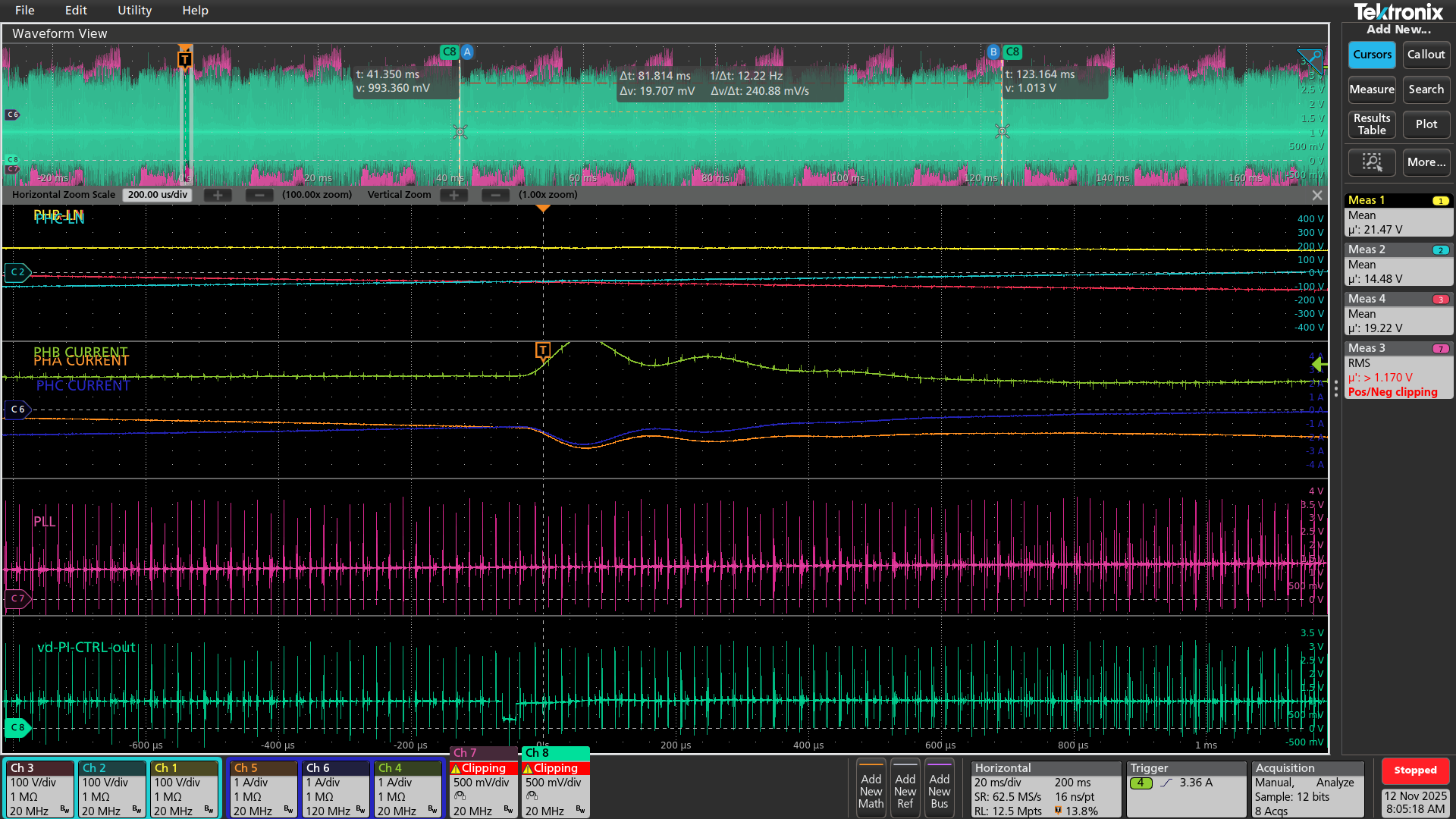
Attached are scope shots of the Vd, Vq, and Current and voltage waveforms and you can see the corrupted data within the current which is coming directly from the SDFM.


Image 1: All Phase Voltages L-to-N, Phase Currents, PLL from DACA, Vq Control Signal from DACB

Vq and PLL.png


Image 2: All Phase Voltages L-to-N, Phase Currents, PLL from DACA, Vd Control Signal from DACB
Vd and PLL.png


Image 1: All Phase Voltages L-to-N, Phase Currents, PHB Current from DACB, PHA Current from DACA

CLOSED LOOP - PHA PH B CURRENT_001.png

  • Hi Noah,

    Just so I understand the issue correctly: the problem at hand is when we see this full-scale +/- "square wave" appear in the DAC outputs, which are derived from the SDFM? 

    Do you have access to a high voltage O-scope probe to check the DC/DC supply on the high side?

    How about a low voltage probe where you can monitor DOUT for long timeout periods where we see constant 1's or 0's in the bitstream? 

    These two points could help use diagnose if the issue is with the AMC3306 isolated ADC or not. 

  • I am not sure if that DAC value is considered to be a railed value or the 63mV specified in the datasheet or not, but the square wave does appear to be the problem through the control loop and we either latch gate signals high when they should not be for a prolonged period of time, or miss a turn on cycle entirely.

    We are looking into probing the DOUT of the AMC3306M05 now. We will be using a MicSig 500MHz BW probe and 500MHz Tektronix Scope for this. We have not checked the HV DC/DC Supply on the high-side. Which pin would you recommend we observe?

  • Please see the attached images of the DOUT Pin.

    For these three images we observed the data on the heatsink and the mean shown my MEAS9/10 is indicating that the data average voltage is 1.833V. The next image shows 1.831V as the current is decaying and the third image just shows the current at a peak to show it appears to be generally the right mean voltage value based on 1s and 0s. This leads us to believe it is how the SDFM is SINC2 filter and when that sampling/processing of data is started. Would you concur with that statement based off the data shown?

    Image 1  Prior to Jump Cycle: Ch1 DACA PH B Current, CH4-6 Phase Currents, Ch 7 PHB Input to AMC3306M05, CH8 Data Out of SDFM

    Image 2 Jump Cycle: Ch1 DACA PH B Current, CH4-6 Phase Currents, Ch 7 PHB Input to AMC3306M05, CH8 Data Out of SDFM

    Image 3 Jump Cycle: Ch1 DACA PH B Current, CH4-6 Phase Currents, Ch 7 PHB Input to AMC3306M05, CH8 Data Out of SDFM

  • Hi Noah, 

    I would. If it was a problem with the data converter, then one possibility would be collapse of the integrated DC/DC power supply requiring a reset cycle. You would monitor this by probing HGND to DCDC_OUT. In the event that this is the case then you would also see the DOUT from the data converter rail either high or low for a duration leading up to the full-scale DAC output, which I thought could help explain the behavior. 

    Since we see DOUT is behaving as expecting I see no need to probe the DC/DC converter and debug should continue with the MCU. 

  • Hello,

    Can you temporarily reduce PWM frequency and observe if spike frequency changes? this will confirm if coupling comming from switching edges.

    These spikes seem to align with switching transitions and possibly phase current crossover points. The PLL and Vq/Vd control outputs also show disturbances at the same instants, which suggests the issue propagates into the control loop.

    The AMC3306 uses a sigma-delta modulator, which is sensitive to common-mode transients. Sampling at the wrong instant can amplify these glitches.

    Can also try Sinc3 filter instead of Sinc2 for better attenuation of high-frequency noise. In hardware-level mitigation, you can consider adding RC filter at the input (e.g., 100 Ω + 1 nF) to attenuate fast transients. Also, isolating power supplies for each AMC3306 if possible, or adding LC filtering on the isolated side.

    Best Regards,

    Masoud

  • Hi Masoud,

    I have reduced the CLK frequency from 20MHz to 10MHz for the SDFM CLK, and the spikes do not change. Yes the spike travels through the control loop, but is not indicated in the data SDFM DOUT data line as shown in the images above. They do align with the phase crossover points which is where a significant portion of the CM will be generated. Above in first post is the control loop propagation traced back to the SDFM filter. I believe we are very close to the correct sampling time, but our CLA is software triggered right now, and I think it should be ePWM1INT triggered so that the control loop and all other ePWMs are in sync for this application. We will try SINC3 filter for noise resilience.

    On the input of the SDFM, we have a 3.3Ohm and a 1uF || 1nF. On the isolated side or phase current side, we have capacitance. We tried adding CM caps and ferrite beads from the shunt resistor, but no luck their either. The issue is very intermittent and sometime it does not show up at all and other times it consistently happens. All of this makes me think the issue is related to SDFM filtering in MCU.

  • I'm reviewing some long open threads and saw this one, apologies I won't be able to follow up later.  Noise on the SDFM CLK can give severe results.  The Usage note in this document (and the datasheet) do cover some mitigations with GPIOQUAL.  Would suggest you look into this if there is system noise which cannot be avoided.  https://www.ti.com/lit/er/sprz412n/sprz412n.pdf#page=10 

  • I added my reply in another thread:  TMS320F28379D: AMC3306 SDFM Corrupted Data 

    Best Regards,

    Masoud