This thread has been locked.

If you have a related question, please click the "Ask a related question" button in the top right corner. The newly created question will be automatically linked to this question.

ADS61B49: About LowSpeed mode

Part Number: ADS61B49

Dear technical Support Team,

As the Christmas season approaches, TI will gradually begin their holiday break, so I would like to resolve this as quickly as possible.

Despite inputting 100MHz, it was no longer operating in LowSpeed mode.
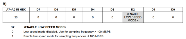
The datasheet states that frequencies below 100MHz use LowSpeed mode, while frequencies above 100MHz use HighSpeed mode. Therefore, we set it to Low.
However, after replacing the ADC, the training pattern output ceased. Debugging revealed that setting it to HighSpeed confirmed pattern output.

(As a background, a failure was confirmed in the ADS61B49IRGZT mounted on the mass-produced boards, and I replaced only this ADC.)

This raises doubts about the datasheet's description regarding operation near 100MHz. We request disclosure of detailed data on this point:

If you could confirm with the designer who developed the ADC, I believe you'll be able to obtain accurate information.

Q1
What is the correct clock range for LowSpeed/Highspeed?

Q2

How does it behave when settings and frequency conflict (e.g., High at 90MHz or Low at 110MHz)?

Best Regards,

ttd

  • Hello TTD,

    My apologies for the late reply. Unfortunately, due to the release date of this device being 17 years ago, I cannot locate any designers within TI to comment further. I have done some research on a similar process device (dual channel), and the low speed mode is rated at 80MHz

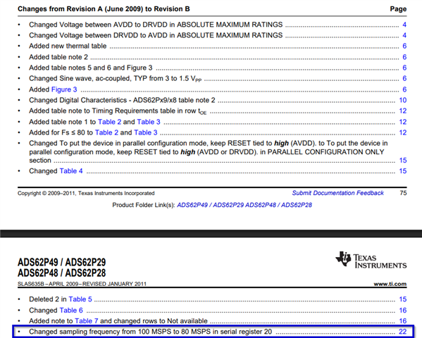
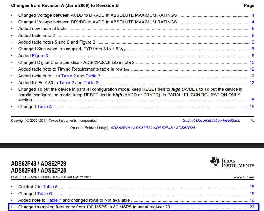
    Change list of the datasheet indicates that the low speed mode was edited from 100MHz to 80MHz during 2009 revision. By similarity to design and process, I suspect the range for low speed mode would be 80MHz for the ADS61B49 as well.

    Would the customer be willing to test if at 80MHz, they can enable low speed mode to check the training pattern? This will help me understand if we can indeed conclude by similarity of process and design.

    My apologies of not able to find designers to further comment.

  • Hi Kang Hsia,

    Thank you for your reply.

    You said:

    Would the customer be willing to test if at 80MHz, they can enable low speed mode to check the training pattern? 

    → I undestand it. I gonna feeback this to my customer. However if 80MHz is correct setting for Lowspeed mode, It seems that revisions to the data sheet will be required.

    It's unfortunate we couldn't find a designer, but it would be great if someone familiar with this device could help.

    I have additaionl question.

    Q3

    The internal block diagram shows a CLOCKGEN. Is this the part whose operation changes based on the High/Low setting?
    Currently, since LVDS is not outputting, I suspect the PLL here couldn't lock and stopped functioning?

    Best Regards,

    ttd

  • Hi Kang Hsia,

    My customer was using a crystal oscillator. Since 100MHz is fixed, we cannot change it to 80MHz and test in Low Speed mode.

    To clarify my question: When operating at 100MHz in HighSpeed mode, the test pattern (custom 0x1555) outputs correctly. Is it acceptable to use HighSpeed mode at 100MHz? 

    I may not be able to locate the designer, but since I've accurately described the current situation, I'd like to share detailed documentation and schematics locally. Could you provide your email address?

    Best Regards,

    ttd

  • Hello TTD-san

    To clarify my question: When operating at 100MHz in HighSpeed mode, the test pattern (custom 0x1555) outputs correctly. Is it acceptable to use HighSpeed mode at 100MHz? 

    Yes, this will be sufficient. The 0x1555 pattern can help ensure the FPGA can capture the pattern with the best setup/hold time. I recommend the customer to try out other patterns. The digital ramp pattern and the toggle pattern will be very beneficial. Could they run the pattern and check if they observe any glitches in the captured data? Could they run this pattern for a few minutes and double check any glitches for potential bit error (BER)? Thank you

    I may not be able to locate the designer, but since I've accurately described the current situation, I'd like to share detailed documentation and schematics locally. Could you provide your email address?

    I will connect with you and you may share with me.

    -Kang

  • Hello TTD-san,

    I have received confirmation that the low speed mode boundary should be moved to 80MHz for the ADS61B49. The next step is for us to submit the datasheet edit request to our TI Datasheet team before we can proceed with datasheet changes. I will keep Ishii-san informed on the process offline.

    Please enable high speed mode for your 100MHz operation

    We should expect datasheet changes similar to the following: