This thread has been locked.

If you have a related question, please click the "Ask a related question" button in the top right corner. The newly created question will be automatically linked to this question.

ADS124S08: ADS124S08 ~10x slower settling than expected

Part Number: ADS124S08

Hello,   

We're using the ADS124S08 wired for RTD measurements, intended to match datasheet applications Figure 2-9 and Figure 2-11.     
   
We're experiencing settling time of ADC readings needing more than 3 seconds to settling.  The long settling time does not seem to be affected by the filter selection.     

Our target settings are 20 SPS internal filter (50ms conversion time) with an external 40Hz analog filter (tau 4ms, 24-bit settling ~60ms).    

So, we're expecting settling within a few hundred milliseconds, but we're measuring settling on the order of 3 seconds.  About 10x worse than expected.    

Any common pitfalls that can cause this discrepency?  

Regards,   

-Jeff   

Attachements:    

Settling of steady state inputs with a fixed 1k resistor in place of an actual RTD:    
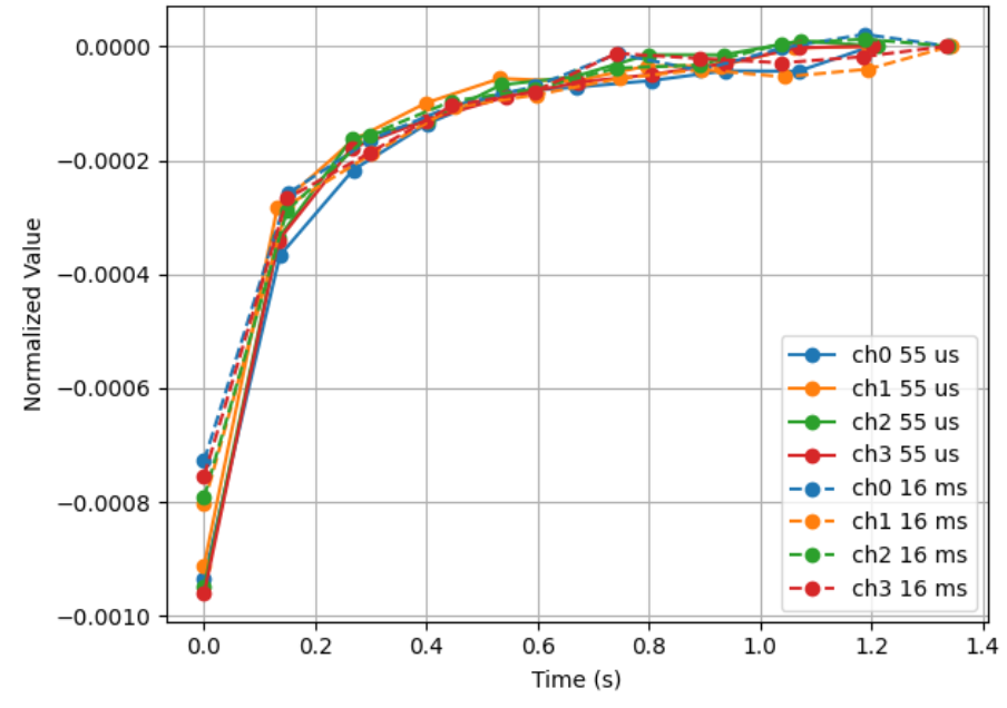
image.png

Schematic snippet as built (intended to match datasheet figures 2-9 & 2-11):    

image.png

  • Hi JSR,

    ADS124S08 datasheet does not have Figure 2-9 and Figure 2-11. I believe you were looking at application report.

    I have some questions:

    1. What's the normalized value in y axis of your graph? What is the difference between ch0 55us and ch0 16ms in terms of configurations and tests?
    2. Did you do the test on a specified channel or you switched the channels with a 1k resistor on each channel? How did you wire them?

    Suggestions:

    1. Ensure that the REFP0 buffer is on and the REFN0 buffer is off (these are the default settings). You should also remove capacitor CPR and CNR from your circuit, select a small capacitor value for CDR, and replace resistor RNR with a 0 ohm resistor. 
    2. Follow up the guideline to select differential input capacitor and common-mode input capacitor, your 1uF capacitor value is high, see the details about input anti-aliasing filtering from the link [FAQ] Delta-sigma ADC anti-aliasing filter component selection.

    BR,

    Dale

  • Hi Dale,

    Thanks for the prompt response.  You are correct, I was looking at the application report not the datasheet; sorry about that.

    Thanks for the FAQ link: in it I notice that my common mode filter caps should be at least 5x smaller.

    Regarding your questions:

    1. Checking on that...

    2. There is a dedicated 1k resistor on each channel.  It is wired exactly like Figure 2-9 in the application report.

    Regarding your suggestions: we will give those a try...

  • Hi JSR,

    After you modify your circuit according to my suggestions and re-capture data, please share your raw data and configurations or software code if possible.

    BR,

    Dale

  • Here are the register settings immediately prior to the measurement: 

    conv_delay: 14
    datarate:   0x15
    dev_id:     0x08
    fscal0:     0x00
    fscal1:     0x00
    fscal2:     0x40
    gpiocon:    0x00
    gpiodat:    0x00
    idacmag:    0x04
    idacmux:    0xf2
    idac_settling_time_ms: 0
    inpmux:     0x01
    ofcal0:     0x00
    ofcal1:     0x00
    ofcal2:     0x00
    pga:        0x08
    ref:        0x12
    settling_time_ms: 10
    status:     0x80
    sys:        0x10
    vbias:      0x00

    The conversion code is: 

    static int ads124s_do_conversion(struct iio_dev *indio_dev,
    				 const struct iio_chan_spec *chan, int *raw)
    {
    	struct ads124s_private *priv = iio_priv(indio_dev);
    	int ret;
    
    	dev_dbg(&priv->spi->dev, "%s\n", __func__);
    	if (priv->meas_type == MEAS_TYPE_THREE_WIRE) {
    		const struct ads124s_rtd_mux *m = &ads124s_rtd_mux_tbl[chan->channel];
    
    		ret = ads124s_write_reg(indio_dev, ADS124S08_INPUT_MUX,
    					(m->ain_p << ADS124S08_POS_MUX_SHIFT) | m->ain_n);
    		
    		ret = ads124s_write_reg(indio_dev, ADS124S08_IDACMUX,
    					(ADS124S08_IDACMUX_OFF << ADS124S08_IDACMUX_I2MUX_SHIFT) |
    					m->ain_idac);
    		if (ret) {
    			dev_err(&priv->spi->dev, "Set IDACMUX failed\n");
    			return ret;
    		}
    		if (priv->idac_settling_time_ms)
    			msleep(priv->idac_settling_time_ms);
    	} else {
    		ret = ads124s_write_reg(indio_dev, ADS124S08_INPUT_MUX,
    					(chan->channel << ADS124S08_POS_MUX_SHIFT) |
    					ADS124S08_AINCOM);
    	}
    	if (ret) {
    		dev_err(&priv->spi->dev, "Set ADC CH failed\n");
    		return ret;
    	}
    		if (priv->settling_time_ms)
    			msleep(priv->settling_time_ms);
    		
    
    	dev_dbg(&priv->spi->dev, "Set ADC Channel\n");
    	
    
    	ret = ads124s_write_cmd(indio_dev, ADS124S08_CMD_START);
    	if (ret) {
    		dev_err(&priv->spi->dev, "Start conversions failed\n");
    		return ret;
    	}
    	dev_dbg(&priv->spi->dev, "conversion started ch%d\n", chan->channel);
    
    	msleep(priv->conversion_time_ms);
    
    	ret = ads124s_read(indio_dev, chan->channel, raw);
    	if (ret < 0) {
    		dev_err(&priv->spi->dev, "Read ADC failed\n");
    		return ret;
    	}
    
    	ret = ads124s_write_cmd(indio_dev, ADS124S08_CMD_STOP);
    	if (ret)
    		dev_err(&priv->spi->dev, "Stop conversions failed\n");
    
    	return ret;
    }

    The device is configured for the "THREE WIRE" measurement type. 

  • Hi JSR,

    Thanks for sharing your register configurations. You are using 3 analog input channels (1 IDAC+2 inputs) for each RTD, but your connection is actually 2-wire RTD measurement. Look forward to your new raw data.

    BR,

    Dale

  • Hi Dale - 

    Totally agree. The meas_type enumerate called "TYPE_THREE_WIRE" is a legacy mis-naming we have been meaning to correct. 

    Or are you referring to something else?  Are we configuring the registers incorrectly for a two wire measurement?

    Thanks,

    sam

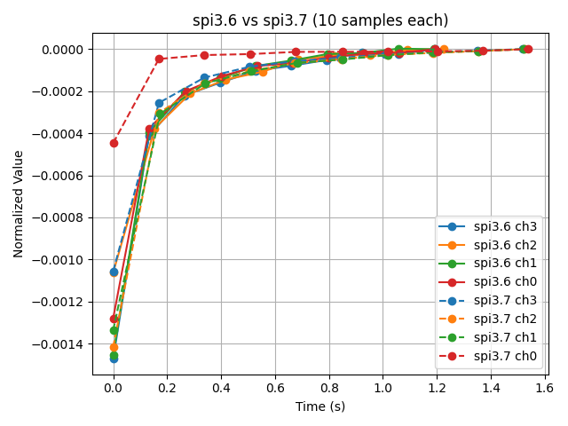
  • We removed CPR and CNR from the circuit, reduced CDR from 1uF to 100 pF. The resulting plot is attached. It compares the unmodified SPI3.6 device from the modified SPI3.7 devices.  Strangely, only the measurement on channel 0 changed.  The others remained unchanged. 

    The plot shows a sequence of 10 measurements for each channel. The Y axis is  "value/last(value) - 1"

       for dev in devices:
            for ch, color in zip(channels, colors):
                t, v = read_channel(dev, f'in_temp{ch}_raw', args.n)

  • The Datasheet includes pseudocode in 10.1.6 for doing multiple measurements of a single channel.  
    Is there an application note or example for cycling through  multiple channels with a single measurement on each channel?

    Second - we do not have access to the DRDY pin to use as a triggered interrupt.  We currently rely on open loop timing (an msleep) to wait for the conversion to finish.  Is there a better way to determine whether the conversion is complete?  

  • Hi Sam,

    I guess you are working with Jeff in the same team.

    Your register configurations look good to me. Your data rate is configured for 50SPS, you are using low-latency and continuous shot mode, so the first data conversion should take 5160*tmod that is 20.156ms when using internal 4.096MHz oscillator, the second and subsequent conversions should take 5120*tmod that is 20ms when using internal 4.096MHz oscillator. Did you replace resistor RNR with a 0 ohm resistor when you did the test?

    You can find the code example in this link.

    All app notes are included in this link.

    Are you checking if the data is ready on the DOUT/DRDY pin 12?

    BR,

    Dale