ADS1261EVM: Configuration Input

Part Number: ADS1261EVM
Other Parts Discussed in Thread: ADS1261-Q1, ADS1261, ADS1248, ADS124S08

Dear Support,

i would like to use ADS1261-Q1 in my application, but i'd like to test some of its features on ADS1261EVM. In my case i have to read 9 PT100 sensors and i was looking for a possible configuration to do that: i read application note SBAA275A "A basic guide to RTD Measurements" and maybe the most suitable solution would be the one reported here below.
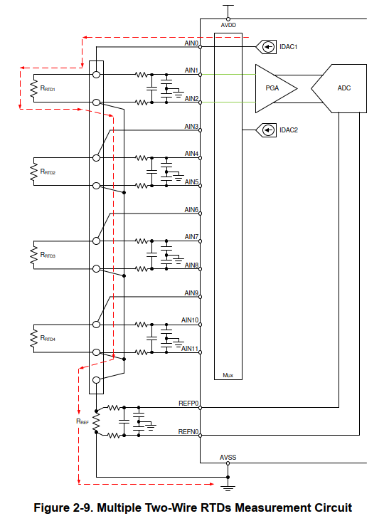
image.png

In my understaing, this would lead to multiple ADS1261 to be used, because one ADS1261 could handle just 2 PT100 (for ADS1261 IN0 and IN1 would be configured as REFP0 and REFN0, and the remaining 8 channel must be configured as 2 differential input and 2 IDAC source). I think that it is not so efficient as solution so i was looking for something different: here below i report a possible configuration that i found in topic for ADS1248.
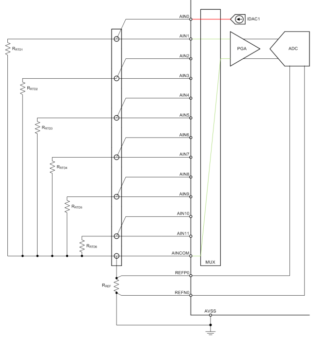
image.png

So my questions are:

  • is ADS1261EVM suitable in order to evaluate all the different configuration i was talking about?
  • Which configuration is the best for 9 PT100 from your point of view ?
  • in the configuration from ADS1248 topic, how do you configure input filter?

Thanks in advance for your help.

Kind regards,

Giorgio

  • Hi Giorgio, 

    Welcome to E2E!

    The main tradeoff of the solution you shared with ADS124S08 is that you cannot have differential filtering. You could put a single-ended filter for each odd AIN channel + AINCOM, but Joseph recommended that schematic if you don't need any input filtering.

    This is the input schematic for the ADS1261EVM:


    You would have to modify the channels you use for the IDAC output to remove the filtering. You could remove the capacitors and replace the series resistors with 0ohm resistors. 

    Thanks, 

    Maggie

  • Hello Maggie,

    thanks for your clarificiations.

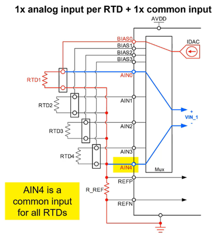
    I would also like what is the difference between referrinf negetive terminals to AINCOM, as saide before, and to REFP as i saw in precision lab series video (i report a screen here below):

    Best regards,

    Giorgio

  • Hi Giorgio, 

    The AINCOM pin can be connected to a level-shift voltage: 

    If a level-shift is not required, then you could use any analog input pin as the common negative input, such as AIN4 in the image you shared. 

    Thanks, 

    Maggie

  • Hi Meggie,

    can i configure ADS1261 as i will show you in order to have 3 RTDs (2 wires config differential reading) :

    - AIN0 and AIN1 are used for REFP and REFN

    - AIN2 is set as IDAC1 and it is used to polarize RTD1 between AIN3 and AIN4 pin (they are set as analog input)

    - AIN5 is set as IDAC1 and it is used to polarize RTD2 beteween AIN6 and AIN7 pin (they are set as analog input)

    AINCOM is set as IDAC1 (from datasheet i understood that i can do this) and it is used to polarize RTD3 beteween AIN8 and AIN9 pin (they are set as analog input)

    For my application it would be nice to have this configuration, let me know what you think.

    BR

    Giorgio

  • Hi Giorgio, 

    Yes, that sounds like a suitable configuration for 2 RTD measurements. And you are correct, the AINCOM pin can act as a current source. 

    You will need to ensure that the three negative inputs are connected to REFP0 so the current can flow through the reference resistor. 

    Thanks, 

    Maggie

  • Hi Maggie,

    thanks for your tips, i think i have all the information needed.

    Giorgio