This thread has been locked.

If you have a related question, please click the "Ask a related question" button in the top right corner. The newly created question will be automatically linked to this question.

ADS1211 ADS1256 same problems with EMI impulse

Other Parts Discussed in Thread: ADS1211, ADS1256, TPD2E001

Hello,

first apologize my bad „German“ English.

Well we have developed  an insulation tester using the ADS1211 for measuring  test voltage 2000 V and the test current e.g. 2 uA.

 When the insulation breaks down or a short circuit happend, an EMI impulse was generated and the ADS1211 was not longer working correct.

The readout was then full scale.  The temperature of the chip heats up after this problem happens.

To solve the problem, we try to use the RESET over the SPI Clock line, but not working.

So the solution was to cut down the AVDD DVDD voltage for short time by relay and switch on again to reset the whole unit.

So far it works with this hack.

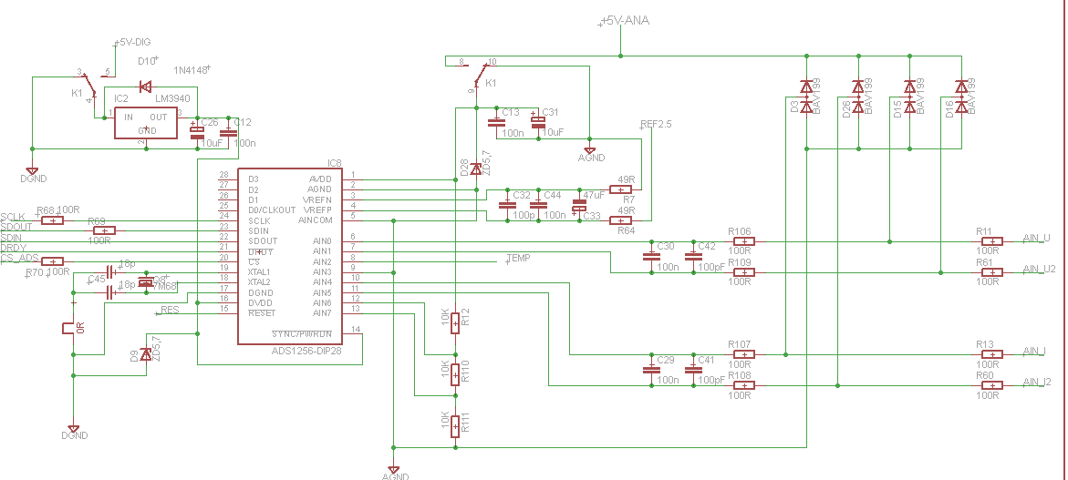
For the next prototype we have changed to the ADS1256 with the hope of a better EMI behavior.

But the same happens with this chip. After the EMI impulse sometimes the sample rate changes, most of the time channel 1 working good, cannel 2 measure 80 % of the expected value, cannel 3 has a higher value.

Also when sending the RESET command, everything was reset (sample rate etc), but the wrong measurement on channel 2 and 3 still exists.

So the only way is to  cut down the whole voltage of the chip.

The hardware reset over the reset pin was not tested until now.

My question is, if the reset command  was executed, why is it not the same as a switch off and on pf the power ? Might the problem caused by latch up effect ? Can I expect a real RESET when I will use the RESET pin ?

I am sure, that the problem was not caused by a noise on the AVD DVDD line.

Regards  Dirk


  • Dirk,

    The problem you describe with the ADS1211 does indeed appear as though the EOS event placed the device into a latch up condition.  It also appears that the ADS1256 has issues that may still be placing the device into an EOS condition.  For the supplies, TVS diodes can be placed near the inputs to prevent overvoltage conditions.  It would also appear that you may need some sort of protection at the analog inputs.  Schottky diode stacks can be used, or some other type of filtering.  For the digital signal lines, devices like the TPD2E001 can be used.

    Best regards,

    Bob B

  • Hi Dirk,

    You had a couple questions here.

    First off, a reset command and a reset pulse will perform the same functionality within the ADS1256. This action is different in comparison to power cycling the device in that the POR does not trigger when a RESET is used. The POR will utilize the one time programmable (OTP) memory to set some of the basic configuration settings for the ADC. In most ADCs, this configuration includes putting the device in normal mode versus some of the internal test modes, setting some of the trim bits if the device has an internal reference, etc. In a lot of devices, a RESET will not reset these OTP bits. Its hard for me to say what exactly is happening to the ADCs once you hit it with an EMI impulse, possibly a latch up.

    Regards,

    Tony Calabria

  • Hello Tony and Bob,

    First of all I am happy to get such a quick and good support from the TI-employees.


    Bob:  Well I have protection diodes on the analogue inputs of the ADS1211 and 1256. I will change from type 1N4148 to type BAV199 next, because of the lower leakage current to increase the measurement accuracy. Sorry I can not find Schottky diodes with a low leakage current. Do you have a recommendation for the series resistors before and after the protection diodes.

    My actual layout is:  Signal from ampilier (Max +-12V)  –>  R100 Ohm –> BAV199 Diodes (to GND and +5V) -> R100 Ohm –>C100nF to groundà  Input ADS.


    Tony: As I understand, the RESET command and the Reset over the pin at the ADS1256 does not do the same as the power up reset.

    Today I made the following test: 

    -        Switch on 1000 V DC test voltage to the test Resistor 1 GOhm

    -        Display of channel 0 is 1000,0xx V (50 % of FSR of ADS)

    -        Display of channel 1 current is about 1.0000 uA (50 % of FSR of ADS)

    -        Display of channel 2 is Temperature 20 Degree Celsius, comes from the sensor inside the reference chip. OK

    -        Produce a short circuit on the test resistor.

    -        Display voltage 1000 V OK, current 0.80xx uA(fail) , Temperature 50 degree Celsius (fail).

    -        Remove test resistor, Current goes to Zerro, connect again, current again 0,8xxx uA.


    So the chip is still working on channel 2 and 3 but with a big error.

    Send the RESET command :  Working, sample rate is changing back to the default value. But measurement still wrong.

    Switch off and on supply voltage AVDD DVDD for 100 ms and reinitialize: Everything OK


    The problem is, that the ADS1211 fails totally, the read out is full scale after EMI impulse, then I make a hard reset by supply voltage switch off.

    But the ADS1256 readout is only 20 % wrong,  so it is difficult to detect such a kind of malfunction.

    Kind regards   Dirk

  • Hello,

    i have totally reworked the design of the PCB layout.

    Digital voltage:  Protected with 3.6 V Z-diode

    Analoge supply:  Also protected with 5.6 V Z-diode.

    Please find below the shematic.

    The new PCB will be finished in a few days, then i can see if the problem with the wrong measurement is still there.

    The relay K1 is to hard-reset the ADS.  R10,11,12  will be used for testing the ADS1256 function. If this measurement is wrong, K1 will be switched off for 1 second.

    My question is:  In the datasheet of the ADS1256 page 28 figure 25 are two resistors 49.9 Ohm shown on the reference input.
    What is the reason for this strange value ? Can i use two 50 Ohm resistors ?

    Thanks in advance.

    Dirk

  • Hi Dirk,

    The 49.9 ohm value is a standard 1% resistor value.  Here is a handy link to standard resistor values:

    http://www.daycounter.com/Calculators/Standard-Resistor-Value-Calculator.phtml


  • Hello,

    well i have finished the new circuit board with all protection parts shown in the above circuit.

    But the ADS1256 is still not running stable, if the EMI impulse happens.

    The ADS will change sample rate afte the Impulse happened.

    A Reset over the Reset pin does not work, so i still have to cut off the power for 200 ms to totally reset the device.

    Dirk.

  • Dirk,

    How do you have your analog and digital grounds connected?  There can never be more than 300mV separation between them.  Can you send us your layout for review.

    Best regards,

    Bob B

  • Hello Bob,

    thanks for your answer.

    Please find attached the Layout and schematic for power supply.

    The analogue and digital ground comes from the ATX plug.

    It is connected in the power plug.

    The ADS1256 is assembled with an adaptor board from SSOP28-DIP28. You can find it below the ESC button between the diodes D9 and D20.

    I think i will make a test and connect both grounds direct under the ADS1256.

    Kind regards  Dirk

    8865.HVT-049b.brd.pdf

    6710.HVT-049b.sch1.pdf

    3288.HVT-049b2.brd.pdf

  • Hello Bob,

    the problem is solved now.

    The reason was was totally different from the things we have discussed until now.

    In my application some SPI devices are connected to the SPI master. The length of the SPI clock line is about 30 cm in total.

    The source of the SPI clock was not terminated with a series resistor. So i think there were some reflections on the clock line.

    So i put a capacitor direct from the SPI clock input pin of the ADS1256 to GND. With the allready existing series  resistor 100 Ohm a low pass filter is working for a SPI frquency of 100 KHz.

    Additional i do a reinitialize of the sample rate every second.

    Now the system runs stable.

    Another question: Can I expect a ADS1256 in DIP case in the future ?

    Kind regards  Dirk

    .

  • Dirk,

    Glad to hear you found your issue.  There are no plans to place the ADS1256 in a DIP package.  There are some manufacturers that make interface boards from SMT to DIP.  These are usually available from the same distributers as the ones where ICs and other components are purchased.

    Best regards,

    Bob B